Method and System of Monitoring Appliance Usage

a technology of monitoring system and appliance usage, applied in the field of method and system of monitoring appliance usage within a building, can solve the problems that the prior art does not discuss or teach the implementation of these functionalities in a coherent way, and achieve the effect of managing energy use effectively and low cos

Inactive Publication Date: 2018-02-01
ENERGY TECH INST
View PDF2 Cites 24 Cited by
  • Summary
  • Abstract
  • Description
  • Claims
  • Application Information

AI Technical Summary

Benefits of technology

[0008]The invention enables complex patterns of utility usage to be used to extract information on what appliances are present within a building and the activities of a person or persons within the building whilst those utilities are being utilised. Advantageously, the method enables deduction of appliance usage patterns, and identification or recognition of appliances or the state of appliances, in a relatively inexpensive way. This is because a low cost set of measurements on utilities at the point of entry into a building can replace or enhance what would otherwise be a much higher number of sensors distributed around the building and its appliances and systems. This in turn adds value to consumers in assisting them to manage their energy use effectively.
[0009]Using more information obtained from monitoring the utilities can allow more details to be determined about the patterns of occupation in the building (i.e. identifying a light switch signature alone would not allow the location of the light to be determined without taking into account other factors—e.g. a tap is running in the bathroom early in the morning so the light is likely to be in the bathroom). Monitoring more than one utility (e.g. electricity and water and possibly also gas) therefore helps to determine which appliances are being used based on expected or probable patterns of appliance usage.
[0040]In effect, aspects of the invention relate to a HEMS that assesses the state of the entire system at regular points in time and tries to determine what is happening. This may include determining what components are being used, what appliances are being used, what work processes are being used and what work flows are in operation. In other words, the system uses utility data to accurately build up a real-time picture of the activities being undertaken in the building at any point in time and may use this to predict a work flow so that the likely energy usage can be supplied. This is contrary to the prior art which relies on nice clean step changes from single utility measurements to identify individual appliances.

Problems solved by technology

The prior art does not discuss or teach about the implementation of these functionalities in any coherent way.

Method used


Image

  • Method and System of Monitoring Appliance Usage
  • Method and System of Monitoring Appliance Usage
  • Method and System of Monitoring Appliance Usage

Examples


Embodiment Construction

[0042]Embodiments of the invention will now be described, by way of example only, with reference to the Figures of the accompanying drawings in which:

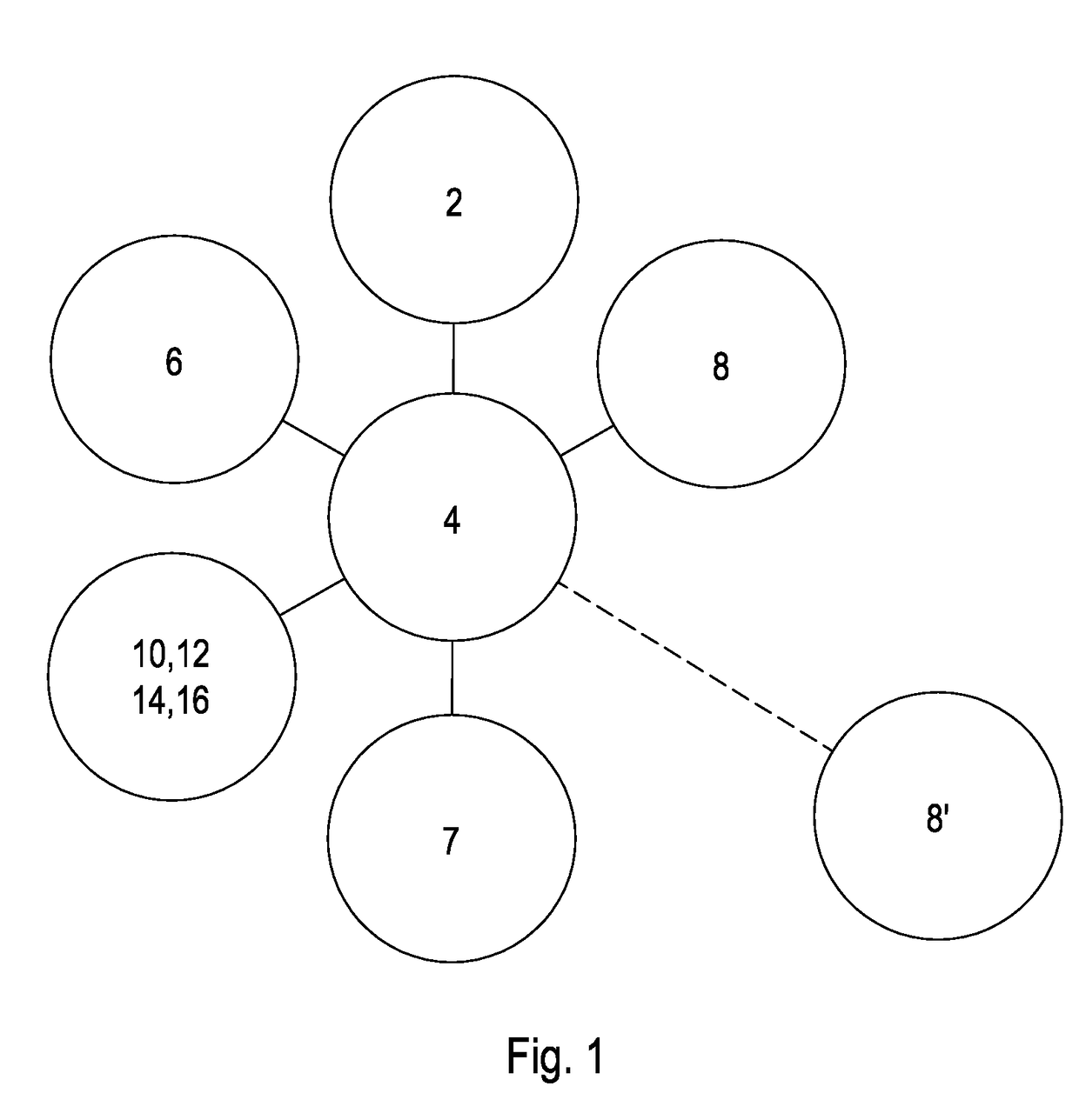
[0043]FIG. 1 shows a schematic representation of an appliance recognition unit in use with a HEMS;

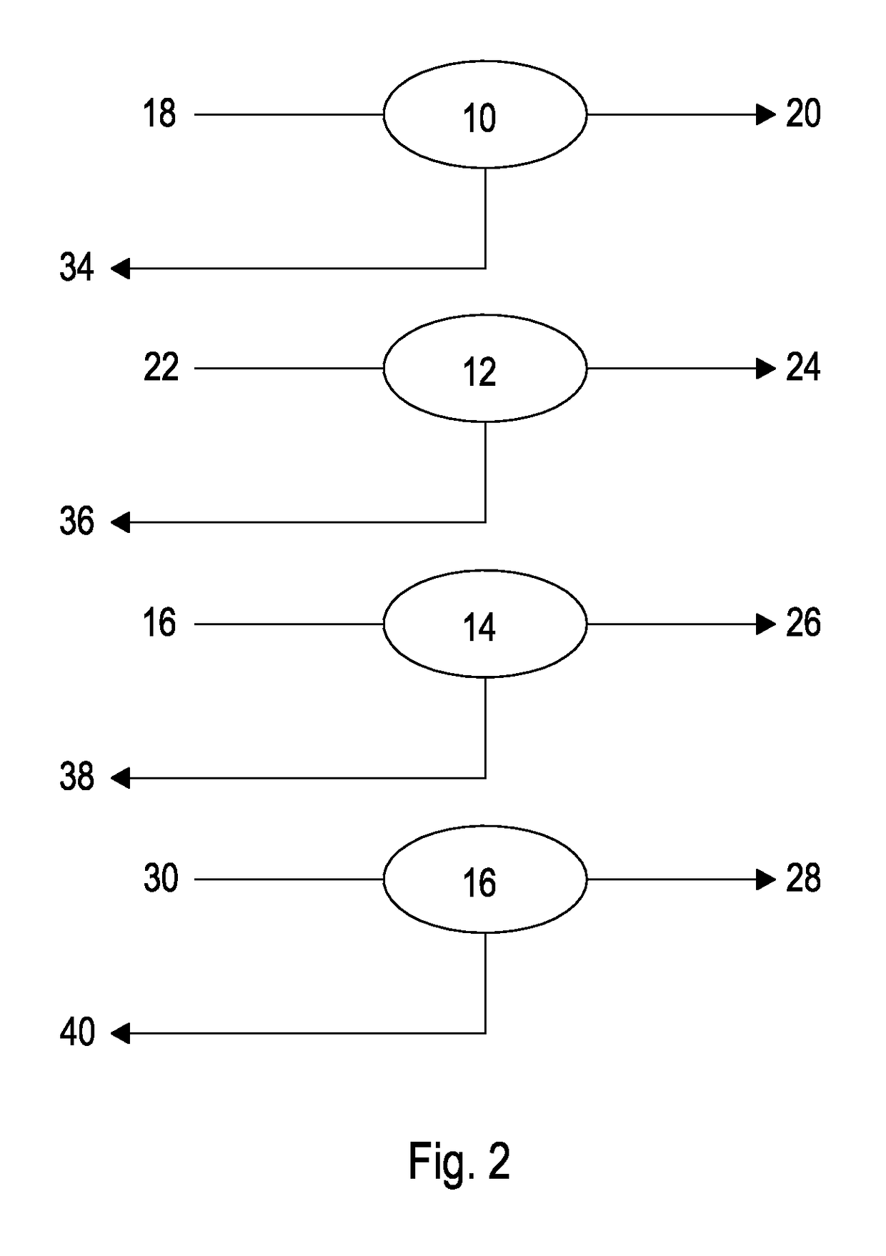
[0044]FIG. 2 shows a schematic representation of utility measurement;

[0045]FIG. 3 is a schematic representation of a finite state analysis of a utility signal channel;

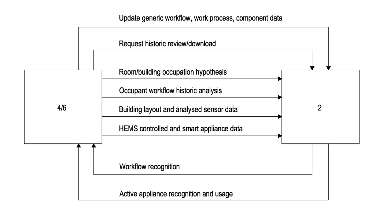
[0046]FIG. 4 is a schematic view of communications between the appliance recognition unit and other modules in a HEMS;

[0047]FIG. 5 is an overview of the hierarchy of appliance operation;

[0048]FIG. 6 illustrates work processes and components in a generic dishwasher;

[0049]FIG. 7a is a graphical representation of daily operation of a bedroom light by month;

[0050]FIG. 7b is a graphical representation of daily operation of a security light by month;

[0051]FIG. 8a is a graphical representation of daily operation of a freezer by room temperature;

[0052]FIG. 8b illustrates three differ...


PUM


Abstract

A method of operating an environment management system within a building, comprises: monitoring appliance usage within the building by monitoring two or more utilities and measuring one or more characteristics relating to each of the utilities to provide an output signal representative thereof; monitoring for changes in the state of each of the output signals at predefined time intervals; combining data from the output signals from each utility, to identify one or more patterns of appliance usage; comparing the identified pattern of appliance usage with stored patterns of appliance usage associated with individual occupants of the building to identify an expected pattern of future appliance usage; and operating the environment management system to control the environment in the building in accordance with the identified expected pattern of future appliance usage.

Description

TECHNICAL FIELD[0001]The present invention relates to a method and system of monitoring appliance usage within a building.BACKGROUND TO THE INVENTION[0002]There are many devices or appliances in dwellings, from individual light fittings, through televisions to major energy users, such as boilers and tumble dryers. In future, some of these devices may be smart, so that they declare their presence and their status can be read, including the possibility of control, such as turning lights on and off to discourage burglars, scheduling drying when power is cheap etc. Some devices will already have this capability (such as Smart TVs and heating systems), although most do not. Understanding patterns of occupancy, appliance use and utility consumption in dwellings currently requires unaffordable levels of instrumentation. Although sensors may eventually be embedded in all devices, including lighting, the timescale for it to be normal to find this level of embedded sensors in the domestic env...

Claims


Application Information

Patent Timeline
Patent Type & Authority Applications(United States)
IPC IPC(8): H04L12/28G06Q10/06G06F9/44G06Q50/06
CPCH04L12/2823G06Q50/06G06Q10/0633G06F9/444G06Q10/06G06F9/4498G05B13/021G05B13/026G06Q50/10
Inventor BROWN, ROGER WARWICKHASLETT, ANDREW MICHAEL
Owner ENERGY TECH INST
Why Eureka
Try Eureka