Decorative sheet

a technology of decorative sheets and carbon fibers, applied in the field of decorative sheets, can solve the problems of poor decorativeness and inability to obtain the texture quality of carbon fibers, and achieve the effect of quality equivalent or higher textur

Inactive Publication Date: 2018-02-08
FUJIFILM CORP
View PDF12 Cites 3 Cited by
  • Summary
  • Abstract
  • Description
  • Claims
  • Application Information

AI Technical Summary

Benefits of technology

[0013]According to the present invention, the image to be observed switches between the first design and the second design by changing the observation direction in which the image forming layer is observed through the lenticular lens sheet. In addition, in the decorative sheet according to the present invention, the image forming layer includes a first sub-divided region having the first design sub-divided in a belt shape, a second sub-divided region having the second design sub-divided in a belt shape, and a belt-shaped intermediate region being formed between the first sub-divided region and the second sub-divided region, in a unit region corresponding to each of the cylindrical lenses. Therefore, quality of a texture equivalent to or higher than that of a real carbon fiber sheet can be obtained.

Problems solved by technology

Therefore, in a carbon texture sheet, the quality of texture of carbon fibers cannot be obtained, and the decorativeness is poor.

Method used


Image

  • Decorative sheet
  • Decorative sheet
  • Decorative sheet

Examples


first embodiment

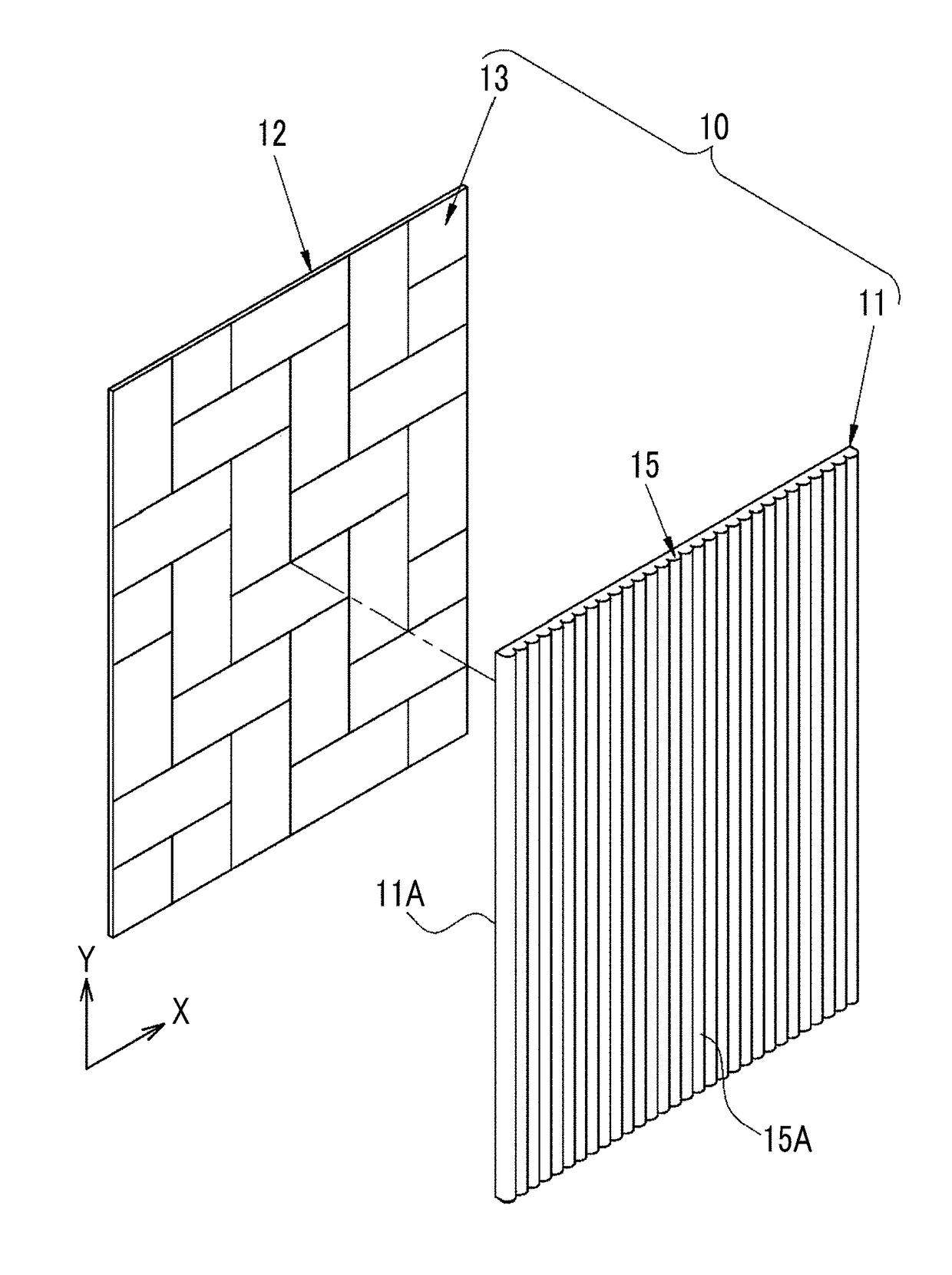
[0024]As shown in FIG. 1, a decorative sheet 10 includes: a lenticular lens sheet 11; and an image forming medium 12 in which an image forming layer 13 is formed. The image forming medium 12 is a transparent resin sheet.

[0025]The lenticular lens sheet 11 includes a plurality of cylindrical lenses 15. Each of the cylindrical lenses 15 includes a convex portion 15A having a partially cylindrical shape, and a surface of the cylindrical lens 15 opposite to the convex portion 15A is flat. Each of the cylindrical lenses 15 extends in a Y direction and is disposed parallel to an adjacent cylindrical lens 15. That is, the cylindrical lenses 15 are disposed at a regular pitch in an X direction perpendicular to the Y direction. The lenticular lens sheet 11 includes a flat surface 11A opposite to the convex portion 15A.

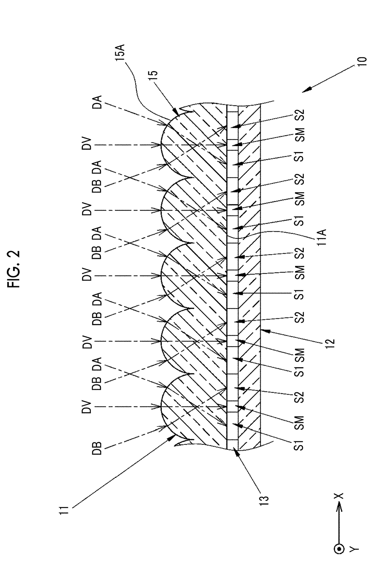
[0026]As shown in FIG. 2, in the decorative sheet 10, the image forming layer 13 is observed from the side including the convex portion 15A of the lenticular lens sheet 11. A cu...

second embodiment

[0058]FIG. 10 shows a lighting device 31 in which the decorative sheet 10 according to the first embodiment is used as a lamp shade. The lighting device 31 includes the decorative sheet 10, a stand 32, a plurality of light sources 33, and a light emitting controller (not shown) that controls light emission of each of the light sources 33.

[0059]The decorative sheet 10 is bent in a cylindrical shape such that the convex portions 15A of the cylindrical lenses 15 are positioned on the outer circumferential surface side. A bending direction is a direction perpendicular to a longitudinal direction (Y direction) of the cylindrical lenses 15. The decorative sheet 10 is supported by the stand 32.

[0060]Each of the light sources 33 is formed of, for example, a light emitting diode (LED) and is supported by a columnar support (not shown). The light sources 33 are disposed in an inner space of the cylindrical decorative sheet 10 at a predetermined interval parallel to each other in the longitudi...


PUM

PropertyMeasurementUnit
angleaaaaaaaaaa
densitiesaaaaaaaaaa
densityaaaaaaaaaa

Abstract

Provided is a decorative sheet capable of obtaining an equivalent or higher quality texture than that of a real carbon fiber sheet. The decorative sheet (10) includes a lenticular lens sheet (11) and an image forming layer (13). The lenticular lens sheet includes a plurality of cylindrical lenses (15). The image forming layer includes a first sub-divided region (Si), a second sub-divided region (S2), and an intermediate region (SM) in a unit region corresponding to each of the cylindrical lenses. By changing an observation direction of the decorative sheet, a first-design (P1), a gradation-design (PG), and a second-design (P2) are sequentially observed. The first-design and the second-design have mutually inverted densities. Images of the first-design, the second-design, and the gradation-design are formed in the first sub-divided region, the second sub-divided region, and the intermediate region, respectively, in a state where they are sub-divided in a belt shape.

Description

CROSS-REFERENCE TO RELATED APPLICATIONS[0001]This application is a Continuation of PCT International Application No. PCT / JP2016 / 056272 filed on Mar. 1, 2016, which claims priority under 35 U.S.C. §119(a) to Japanese Patent Application No. 2015-092621 filed on Apr. 30, 2015. Each of the above application(s) is hereby expressly incorporated by reference, in its entirety, into the present application.BACKGROUND OF THE INVENTION1. Field of the Invention[0002]The present invention relates to a decorative sheet that is bonded to an interior part or an exterior part of an automobile or the like.2. Description of the Related Art[0003]A technique of bonding a carbon fiber sheet to an interior part or an exterior part of an automobile or the like for decoration is disclosed (for example, refer to JP3847406B). However, a carbon fiber sheet is obtained by weaving carbon fibers by twill weaving in a sheet shape, and is extremely expensive. Therefore, a carbon texture sheet has been widely used i...

Claims


Application Information

Patent Timeline
Patent Type & Authority Applications(United States)
IPC IPC(8): G02B27/22B60R13/02B32B27/08G02B3/00B32B3/30B32B33/00G02B30/29
CPCG02B27/2214B32B3/30B32B33/00B32B27/08G02B3/005B60R13/02B32B2605/003B32B2451/00B32B7/12B32B27/308B32B27/32B32B27/36B32B27/365B32B2250/02B32B2250/24B32B2307/4023B32B2307/404G02B30/29G02B30/27
Inventor NAKAMURA, SAMITOTAKENOSHITA, HIROMIABIRU, DAISAKU
Owner FUJIFILM CORP
Why Eureka
Try Eureka