
Scan geometry planning method for MRI or ct

Inactive Publication Date: 2018-02-15
KONINKLJIJKE PHILIPS NV
View PDF2 Cites 2 Cited by
  • Summary
  • Abstract
  • Description
  • Claims
  • Application Information

AI Technical Summary

Benefits of technology

The patent text aims to provide a centralized and automatic approach for scan geometry planning to increase the accuracy of acquired image data obtained from multiple scanning imaging systems. This approach involves using reference images stored in a database, which speed up the acquisition process compared to 3D survey images. The technical effect of this patent is to improve the accuracy and efficiency of scanning imaging systems.

Problems solved by technology

This is a complicated and also labour intensive development and research task and needs a huge amount of resources.

Method used


Image

  • Scan geometry planning method for MRI or ct
  • Scan geometry planning method for MRI or ct
  • Scan geometry planning method for MRI or ct

Examples


Embodiment Construction

[0045]In the following, like numbered elements in the figures are either similar elements or perform an equivalent function. Elements which have been discussed previously will not necessarily be discussed in later figures if the function is equivalent.

[0046]Various structures, systems and devices are schematically depicted in the figures for purposes of explanation only and so as to not obscure the present invention with details that are well known to those skilled in the art. Nevertheless, the attached figures are included to describe and explain illustrative examples of the disclosed subject matter.

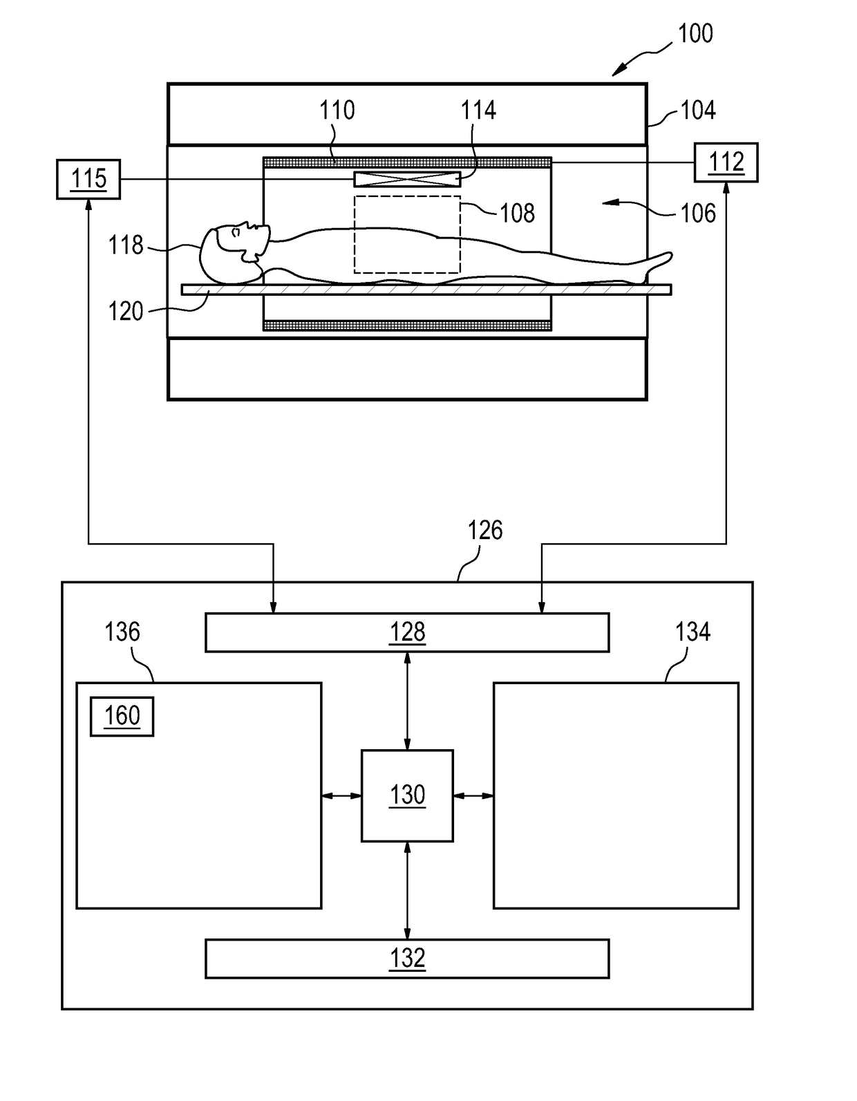
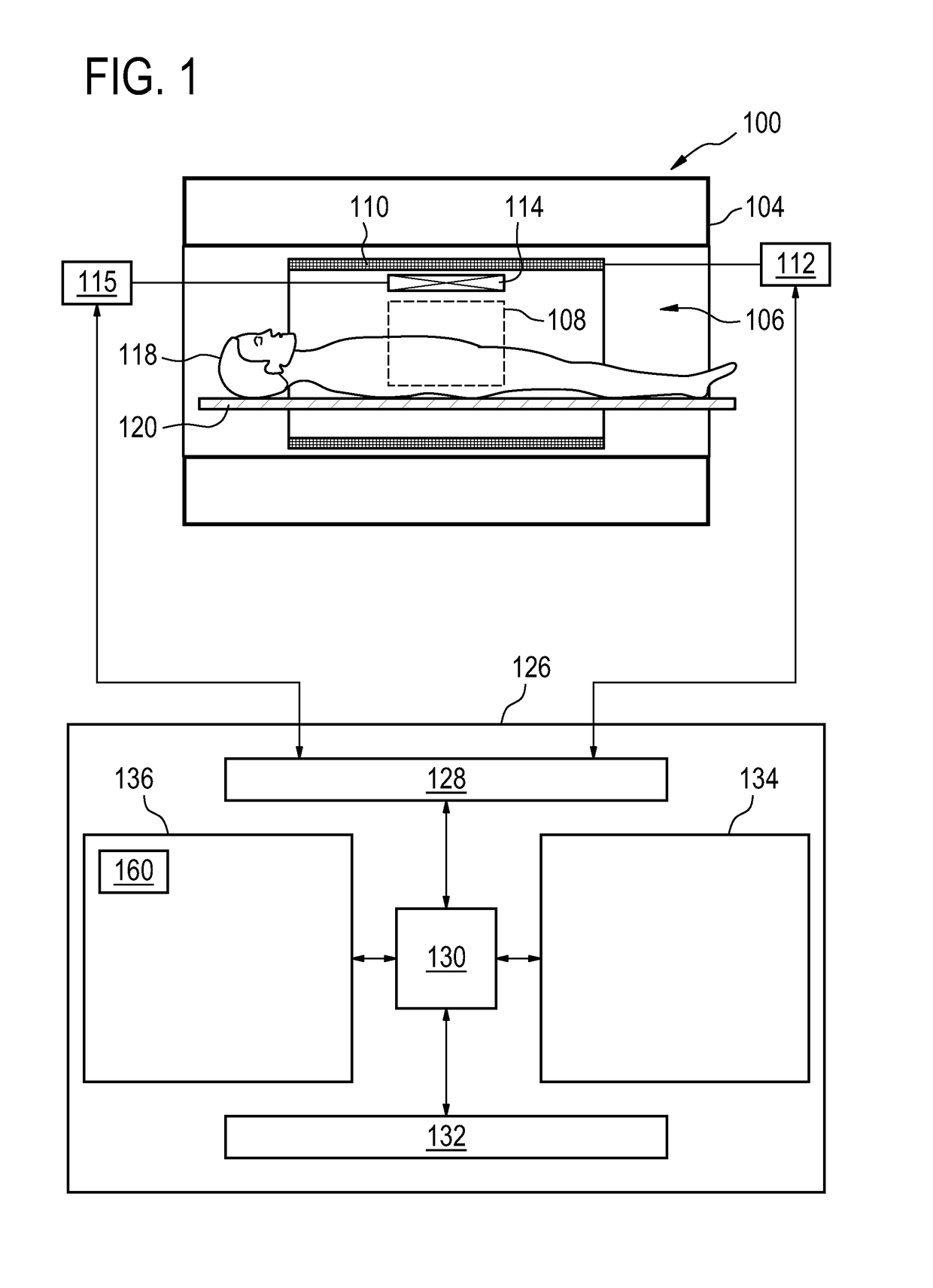
[0047]FIG. 1 illustrates an example scanning imaging system being a magnetic resonance imaging system 100. The magnetic resonance imaging system 100 comprises a magnet 104. The magnet 104 is a superconducting cylindrical type magnet 100 with a bore 106 through it. The use of different types of magnets is also possible for instance it is also possible to use both a split cylindrical magn...


PUM


Abstract

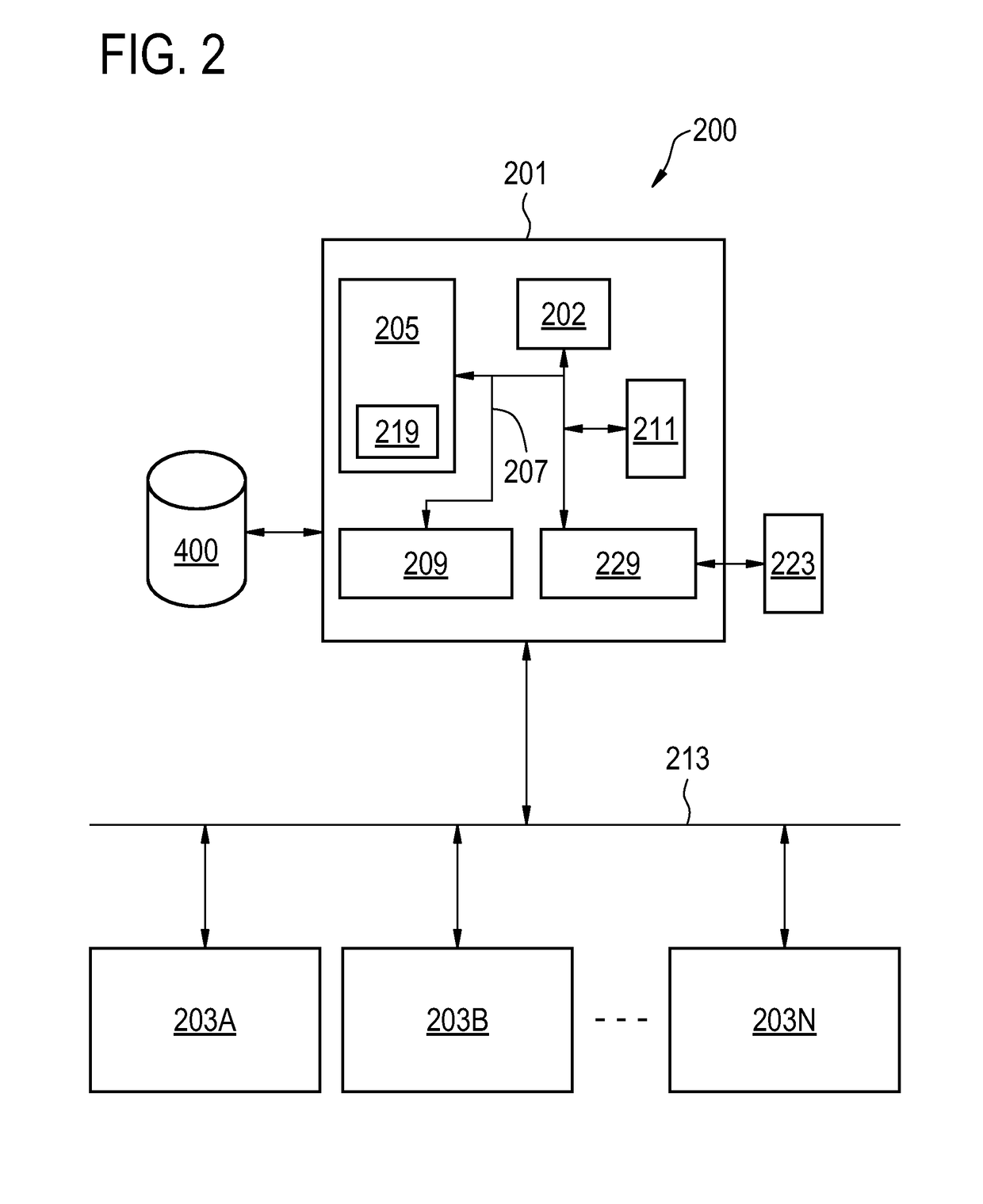
The present invention relates to a method for scan geometry planning. The method comprises: providing at least one scanning imaging system (203A-N, 100) coupled to a computer server (201); controlling the server (201) to communicate with the at least one scanning imaging system (203A-N); building a database (400) from image data obtained from the at least one scanning imaging system, wherein the image data indicates scan 5 geometries in association with respective reference images acquired using the scan geometries; receiving at the server (201) a scan geometry request from a scanning imaging system (203A) of the at least one scanning imaging system, the request being indicative of a survey image, wherein the survey image is obtained during a calibration scan by imaging a patient by the requesting scanning imaging system (203A); comparing the survey image with 10 the reference images; sending the requesting scanning imaging system data indicative of a scan geometry associated with a reference image of the reference images that matches the survey image; controlling the requesting scanning imaging system (203A) to acquire imaging data during a clinical scan of the body volume using one of the submitted scan geometry and a modified scan geometry that results from the modification of the submitted scan geometry 15 at the requesting scanning imaging system; controlling the requesting scanning imaging system (203A) to send the modified scan geometry to the server (201) in case the modified scan geometry is used for the acquiring of imaging data.

Description

TECHNICAL FIELD OF THE INVENTION[0001]The invention relates to scanning imaging systems, in particular to a method of scan geometry planning.BACKGROUND OF THE INVENTION[0002]Automation and simplification of scanning imaging systems such as magnetic resonance imaging (MRI) systems is currently in the focus of research. One important feature that enables the fully automated magnetic resonance acquisition is automated planning of scan geometries.[0003]The extension of automated scan planning methods to different anatomies and organs requires the development of anatomical models together with models for an expected image contrast for each anatomy and acquisition protocol. This is a complicated and also labour intensive development and research task and needs a huge amount of resources.[0004]U.S. Pat. No. 8,144,955 concerns the automatic computation of a geometry plan from input landmark details. The US-patent application US2002 / 0198447 concerns a prescription of scanning parameters (sca...

Claims


Application Information

Patent Timeline
IPC IPC(8): G01R33/54A61B6/03A61B6/00A61B5/055
CPCG01R33/543G01R33/546A61B5/055A61B6/032A61B6/545A61B6/563A61B6/566A61B6/582A61B6/488
Inventor NIELSEN, TIMKOKEN, PETER
Owner KONINKLJIJKE PHILIPS NV
Learn More