
Multi-resolution fmcw radar detection method and radar implementing such a method

a radar detection and multi-resolution technology, applied in the field of multi-resolution radar detection methods, can solve the problems of affecting processor load, affecting processor load, and affecting the cost of the sensor

Active Publication Date: 2018-02-15
THALES SA
View PDF3 Cites 35 Cited by
  • Summary
  • Abstract
  • Description
  • Claims
  • Application Information

AI Technical Summary

Benefits of technology

The invention is a radar target-detection method that uses an FMCW waveform with a recurring pattern. The method includes a distance compression processing operation, a Doppler processing operation, and a second distance compression processing operation. The method can detect both stationary and moving targets at different speeds with high accuracy. The invention also provides an FMCW radar that can implement this method.

Problems solved by technology

Moreover, as regards automotive radars, the cost of the sensor is extremely constrained, and the available computational resources are therefore limited.
One technical problem to be solved is that of obtaining a satisfactory discrimination capacity while limiting the impact on processor load.
To this day, this problem has not been solved or not satisfactorily.
This leads to a decrease in waveform efficiency since the various emission patterns share the radar integration time.
Distance resolution is relatively low, typically of a few metres, and does not allow a sufficient discrimination of obstacles to automatically engage emergency braking at high speeds.
Here again, the number of distance boxes to be processed remains modest because of the low resolution, even though the distance domain is larger.

Method used


Image

  • Multi-resolution fmcw radar detection method and radar implementing such a method
  • Multi-resolution fmcw radar detection method and radar implementing such a method
  • Multi-resolution fmcw radar detection method and radar implementing such a method

Examples


Embodiment Construction

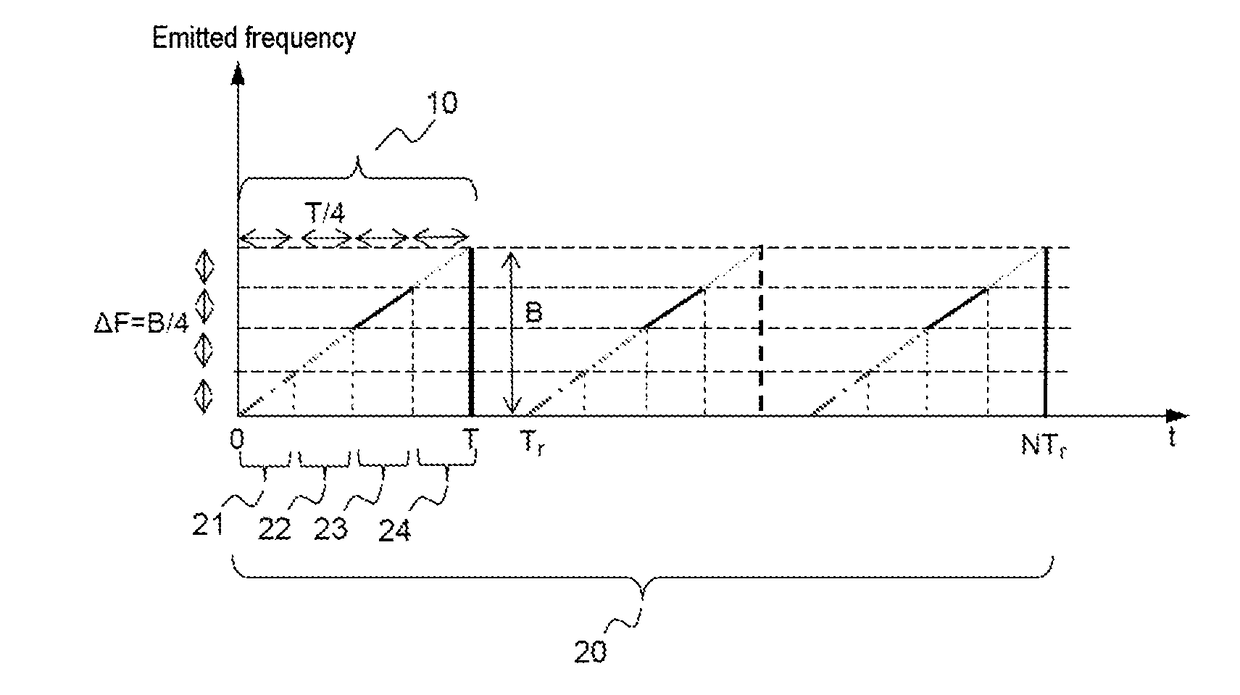
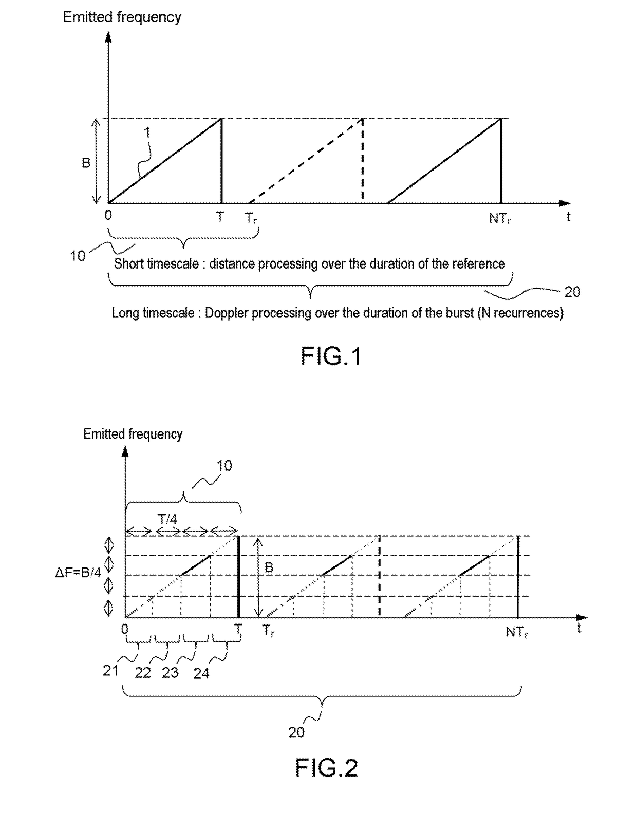
[0037]FIG. 1 recalls the prior art. More particularly, it illustrates the modulation of the emitted frequency, this modulation being of FMCW type.

[0038]Generally, an automotive radar mounted on a vehicle, and the beam of which is oriented toward the front of the latter, will be considered. This radar implements a linearly frequency-modulated waveform according to the FMCW principle, well known to those skilled in the art, and as shown in FIG. 1. A first processing operation is carried out on a short timescale, at the scale of the recurrence 10 of duration Tr, aiming to separate the received signals via direct demodulation followed by digitisation of the signals and a P-point FFT, the P points corresponding to the duration of the frequency ramp 1.

[0039]This operation carries out a compression on the distance axis. On output from this processing operation, the signals are distributed into P / 2 ambiguous distance boxes, the beat frequency fb of a received signal corresponding to a dista...


PUM


Abstract

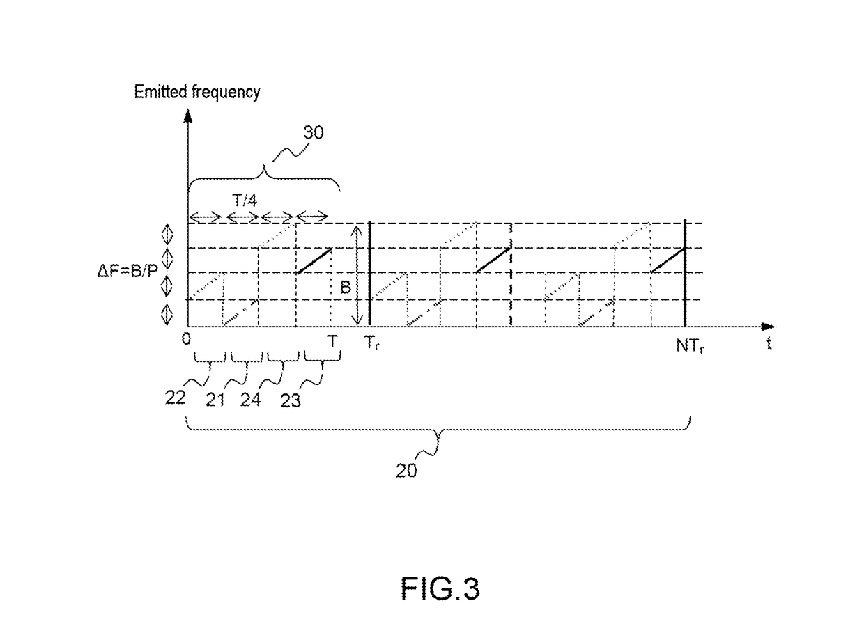
A detection method implementing an FMCW waveform is provided, the emitted waveform is formed of a recurring pattern of given period Tr covering an emission frequency band of given width B, each pattern being divided into a given number P of sub-patterns of duration Tr / P covering an excursion frequency band ΔF=B / P, the sub-patterns being mutually spaced by a frequency interval equal to ΔF. The radar performs: a first distance-compression processing operation carrying out a low-resolution distance compression at the scale of each recurring pattern on a fraction B / P of the emission band of width B corresponding to the frequency band covered by each of the sub-patterns; a Doppler processing operation on a given number N of successive recurrences so as to form P ambiguous distance-Doppler maps of low distance resolution, the maps being segmented into various speed domains; a second distance-compression processing operation of resolution that differs depending on the speed domain to which the relative speed of the target with respect to the radar belongs.

Description

CROSS-REFERENCE TO RELATED APPLICATIONS[0001]This application claims priority to foreign French patent application No. FR 1601224, filed on Aug. 11, 2016, the disclosure of which is incorporated by reference in its entirety.FIELD OF THE INVENTION[0002]The present invention relates to a multi-resolution radar detection method employing an FMCW emission wave. It also relates to a radar implementing such a method. The invention is in particular applicable to the field of automotive radars. More generally it may be applicable to FMCW radars.BACKGROUND[0003]Automotive radars have been integrated into driver aids the role of which is rather to increase comfort: for example adaptive cruise controllers (ACC) for use on motorways or controllers with “Stop and Go” functionality for use in urban driving. They use microwaves and in particular the 76-81 GHz band.[0004]Technological progress has allowed present-day applications to also target anticollision-type safety functions, and it is also en...

Claims


Application Information

Patent Timeline
IPC IPC(8): G01S13/34G01S13/60G01S13/93G01S13/50G01S13/36G01S13/28G01S13/931
CPCG01S13/34G01S13/36G01S13/605G01S13/93G01S13/505G01S13/28G01S13/343G01S13/931G01S7/356G01S7/0235G01S7/0232G01S13/584
Inventor CORNIC, PASCALLE BIHAN, PATRICKQUELLEC, JEAN-MICHEL
Owner THALES SA
Learn More