Apparatus for a Near-Eye Display

a technology for eye displays and eye monitors, applied in eye diagnostics, television systems, instruments, etc., can solve problems such as the optimal use of conventional eye monitors with integrated gaze tracking functionality systems

Active Publication Date: 2018-02-15
MAGIC LEAP INC
View PDF4 Cites 99 Cited by
  • Summary
  • Abstract
  • Description
  • Claims
  • Application Information

AI Technical Summary

Problems solved by technology

Conventional near-eye displays with integrated gaze tracking functionality systems are not always optimal, not least for example in view of the additional components as well as increased complexity, size and weight necessary to incorporate both gaze tracking functionality as well as display functionality in a near-eye display.

Method used


Image

  • Apparatus for a Near-Eye Display
  • Apparatus for a Near-Eye Display
  • Apparatus for a Near-Eye Display

Examples


Embodiment Construction

[0040]Examples of apparatuses according to the present disclosure will now be described with reference to the Figures. Similar reference numerals are used in the Figures to designate similar features. For clarity, all reference numerals are not necessarily displayed in all figures.

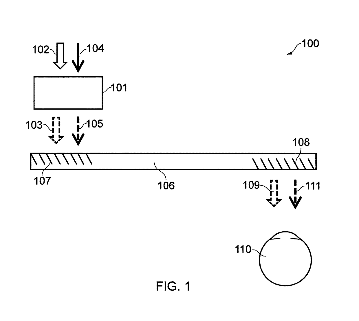
[0041]FIG. 1 schematically illustrates a block diagram of an apparatus 100 according to an example of the present disclosure. FIG. 1 focuses on the functional components necessary for describing the operation of the apparatus.

[0042]The apparatus 100 comprises a light modulator 101 configured to receive light of a first range of wavelengths 102, and generate an image beam 103 therefrom. The light modulator 101 is further configured so as to receive light of a second range of wavelengths 104 and generate a probe beam 105 therefrom.

[0043]The apparatus 100 further comprises one or more light guides 106 comprising one or more in-coupling diffractive element areas 107, and one or more out-coupling diffractive el...


PUM


Abstract

An apparatus for providing gaze tracking in a near-eye display. Certain examples provide an apparatus including a light modulator configured to receive light of a first range of wavelengths and generate an image beam therefrom. The light modulator is further configured to receive light of a second range of wavelengths and generate a probe beam therefrom. The apparatus also includes one or more light guides including one or more in-coupling element areas, and one or more out-coupling element areas. The one or more in-coupling element areas are configured to receive and in-couple the image beam and the probe beam into the one or more light guides. The one or more out-coupling element areas are configured to out-couple, from the one or more light guides: the image beam to a user's eye for user viewing, and the probe beam to the user's eye for detection of reflection therefrom.

Description

TECHNOLOGICAL FIELD[0001]Examples of the present disclosure relate to an apparatus for a near-eye display. Some examples, though without prejudice to the foregoing, relate to an apparatus for providing gaze tracking in a near-eye display.BACKGROUND[0002]Gaze tracking, namely the process of determining a point of gaze of a user's eye so as to determine a line of sight associated with the user's eye or to determine where the user is looking (and thus determining what the user is looking at), typically relies on capturing video images from a user's eye(s). Such video based gaze tracking typically uses infrared (IR) LEDs or infrared lasers for illuminating the eye and detecting reflections / glints of the infrared light from the eye (e.g. its cornea / surface). A determination of a user's gaze may be calculated based on the detected IR reflections and detected eye features such as detected pupil position. Conventional near-eye displays with integrated gaze tracking functionality systems are...

Claims


Application Information

Patent Timeline
Patent Type & Authority Applications(United States)
IPC IPC(8): G06K9/00G02B5/20H04N5/225G02B27/00H04N5/33H04N5/235F21V8/00G02B27/01
CPCG06K9/00604G02B6/0016G02B6/0036G02B5/208G02B27/0172G02B27/0093H04N5/332H04N5/2354H04N5/2256G02B2027/0138G02B2027/0112G02B2027/0123G02B2027/0178G06K2209/21G02B2027/0125G02B2027/0132G02B27/4205A61B3/113G06V40/19G06V2201/07H04N23/11H04N23/56H04N23/74
Inventor JARVENPAA, TONI
Owner MAGIC LEAP INC
Why Eureka
Try Eureka