HIGH pH ORGANIC FLOW BATTERY
a high-ph organic flow and battery technology, applied in the direction of fuel cells, regenerative fuel cells, basic electric elements, etc., can solve the problem of large storage of energy, and achieve the effects of high solubility, high stability, and fast kinetics
- Summary
- Abstract
- Description
- Claims
- Application Information
AI Technical Summary
Benefits of technology
Problems solved by technology
Method used
Image

Examples
example 1
[0113]The positive electrolyte was prepared by dissolving potassium ferrocyanide trihydrate (1.9 g) and potassium ferricyanide (0.15 g) in 1 M KOH solution (11.25 mL) to afford a 0.4 M ferrocyanide +40 mM ferricyanide electrolyte solution. The negative electrolyte was prepared by dissolving riboflavin 5′ phosphate sodium salt (0.72 g) in 2 M KOH solution (3 mL) resulting a 0.5 M electrolyte solution.
[0114]The negative electrolyte was prepared at a fully oxidized state. The positive electrolyte contained 9% oxidized species.
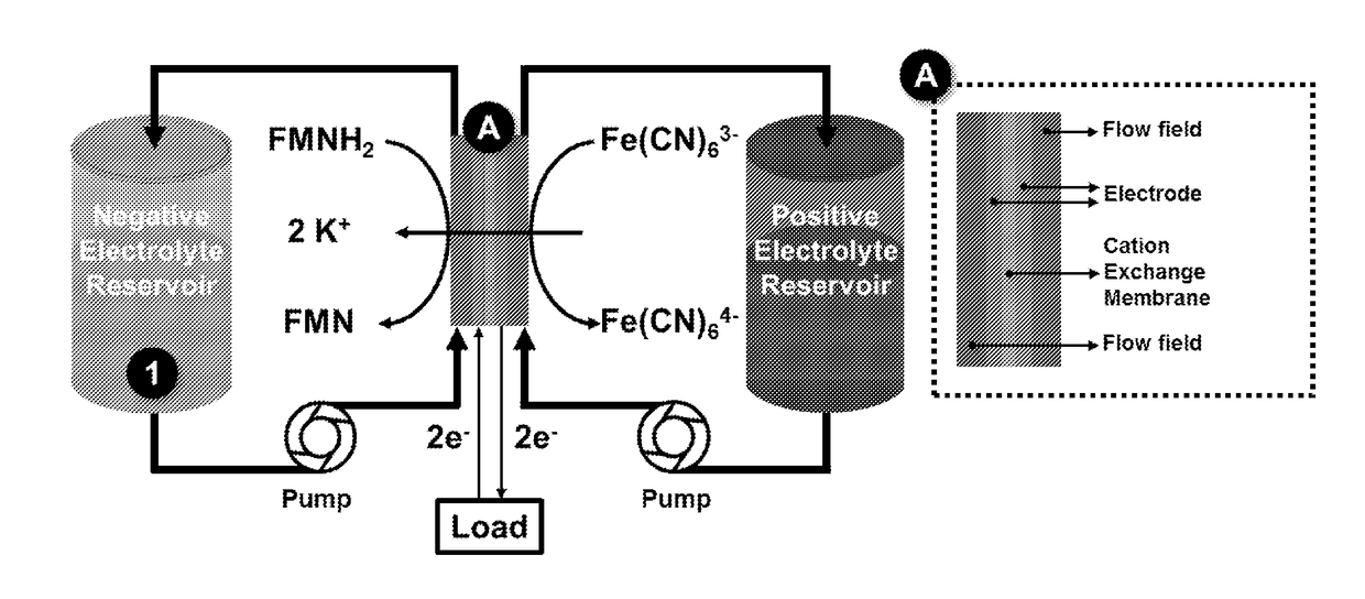
[0115]Hardware from Fuel Cell Tech. (NM, Albuquerque) was used to assemble a zero-gap flow cell configuration, similar to previous reports (Aaron, D. S. et al. Journal of Power Sources 206, 450-453 (2012)), and shown schematically in FIG. 4. Serpentine flow pattern flow plates were used for both sides. A 5 cm2 geometric surface area electrode comprised a stack of three pieces of SGL Sigracet GDL 10AA porous carbon, and a piece of Nafion 212 membrane served as the ...
example 2
[0118]The positive electrolyte was prepared by dissolving potassium ferrocyanide trihydrate (3.2 g), sodium ferrocyanide decahydrate (3.6 g) and potassium ferricyanide (0.5 g) in 0.5 M KOH +0.5 M NaOH solution (15 mL) to afford a 1 M ferrocyanide +0.1 M ferricyanide electrolyte solution. The negative electrolyte was prepared by dissolving riboflavin 5′ phosphate sodium salt (2.4 g) in 4 M KOH solution (5 mL) resulting a 1 M electrolyte solution. The negative electrolyte was prepared in a fully oxidized state. The positive electrolyte contained 9% oxidized species.
[0119]Hardware from Fuel Cell Tech. (NM, Albuquerque) was used to assemble a zero-gap flow cell configuration, similar to previous reports (Aaron, D. S. et al. Journal of Power Sources 206, 450-453 (2012)), and shown schematically in FIG. 4. Serpentine flow pattern flow plates were used for both sides. A 5 cm2 geometric surface area electrode comprised a stack of three pieces of SGL Sigracet GDL 10AA porous carbon, and a pi...
example 3
[0121]Synthesis of a mixture of the isomeric structures alloxazine 7-carboxylic acid and alloxazine 8-carboxylic acid was carried out following the literature (Liden, A. A. et al. The Journal of Organic
[0122]Chemistry 71, 3849-3853 (2006)). 3,4-diaminobenzoic acid (5 g; purchased from VWR) was added to 250 mL acetic acid with gentle stirring. Boric acid (2.5 g; purchased from Sigma Aldrich) and alloxane monohydrate (5.25 g; purchased from VWR) were added to the solution. The reaction mixture was allowed to react under inert atmosphere for 3 hours. The greenish yellow product was vacuum filtered, washed with acetic acid, followed by water and finally by diethyl ether, and dried under vacuum. The 1H NMR spectrum shown in FIG. 9 matched literature value. This mixture of the isomeric structures alloxazine 7-carboxylic acid and alloxazine 8-carboxylic acid was used for subsequent battery tests without further purification.
PUM
 Abstract
Description
Claims
Application Information