Frequency-compensated transconductance amplifier

a transconductance amplifier and frequency compensation technology, applied in the direction of dc-amplifiers with dc-coupled stages, amplifiers with semiconductor devices/discharge tubes, and different amplifiers, can solve the problems of reducing the unity-gain bandwidth of the transconductance amplifier is reduced, and the compensation effect is limited

Active Publication Date: 2018-02-22
NO 24 RES INST OF CETC
View PDF3 Cites 4 Cited by
  • Summary
  • Abstract
  • Description
  • Claims
  • Application Information

AI Technical Summary

Benefits of technology

[0015]In the frequency-compensated transconductance amplifier provided by the present invention, the frequency compensation network formed by sequentially connecting the gain stage GAIN, the compensating capacitor Rc and the compensating capacitor Cc in series enables the generation of a left half-plane zero point of a very low frequency, and the left half-plane zero point of the very low frequency enables pole-zero cancellation with a first non-dominant pole of the transconductance amplifier, and compared with the traditional compensation method for the transconductance amplifier, the compensation technology provided by the present invention does not decrease the frequency of the dominant pole; and meanwhile, the generated low-frequency left half-plane zero point and the first non-dominant pole undergo cancellation, which may improve the amplitude-frequency characteristic curve of the transconductance amplifier to allow the curve to rise at a high frequency, thereby greatly increasing the unity-gain bandwidth of the transconductance amplifier and guaranteeing an ideal phase margin while significantly improving a factor of mass for the transconductance amplifier.

Problems solved by technology

Or, a larger phase margin is obtained by introducing a left half-plane zero point with a passive frequency compensation technology to undergo cancellation with a first non-dominant pole, but the passive compensation technology may also reduce the frequency of the first non-dominant pole at the same time, and both the zero point of a transmission function and the pole may be affected by a compensating capacitance, resulting in an insignificant zero-pole cancellation effect.
Therefore, the traditional compensation technology hardly meets various requirements of a high-performance transconductance amplifier at the same time.
However, this compensation method has the disadvantage that the transconductance amplifier has a −3 dB width reduction due to the movement of the dominant pole of the transconductance amplifier to a lower frequency, which greatly reduces the unity-gain bandwidth of the transconductance amplifier.
Therefore, a compensation effect achieved with the compensation technology shown by the structure 2 is also limited.

Method used


Image

  • Frequency-compensated transconductance amplifier
  • Frequency-compensated transconductance amplifier
  • Frequency-compensated transconductance amplifier

Examples


Embodiment Construction

[0030]For a better understanding of the implemented technical means, inventive features, and achieved objects and effects of the present invention, the present invention will be further illustrated below in combination with specific drawings.

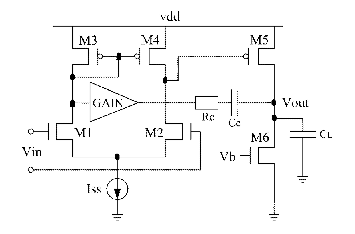
[0031]Referring to FIG. 4, the present invention provides a frequency-compensated transconductance amplifier. The frequency-compensated transconductance amplifier includes an input stage of the transconductance amplifier, a first-stage active load of the transconductance amplifier, a first-stage tail current source of the transconductance amplifier, a second-stage input transistor of the transconductance amplifier, a load capacitor of the transconductance amplifier, and a frequency compensation network of the transconductance amplifier. The input stage of the transconductance amplifier is consisting of NMOS transistors M1 and M2. The first-stage active load of the transconductance amplifier is consisting of PMOS transistors M3 and M4. The first-...


PUM


Abstract

The present invention provides a frequency-compensated transconductance amplifier, includes an input stage consisting of NMOS transistors M1 and M2, a first-stage active load consisting of PMOS transistors M3 and M4, a first-stage tail current source consisting of a constant current source Iss, a second-stage input transistor consisting of a PMOS transistor M5, a second-stage constant current source consisting of an NMOS transistor M6, a load capacitor consisting of a capacitor CL, and a frequency compensation network formed by sequentially connecting a gain stage GAIN, a compensating resistor Rc and a compensating capacitor Cc in series.

Description

BACKGROUND OF THE INVENTIONTechnical Field[0001]The present invention belongs to the technical field of analog or digital-analog hybrid integrated circuits, and in particular to a frequency-compensated transconductance amplifier.Description of Related Art[0002]With the continuous development of an integrated circuit design technology in recent years, more and more transconductance amplifiers have been applied to the field of analog integrated circuit designs. In most of the application scenarios of the transconductance amplifier, frequency compensation is performed on the transconductance amplifier in order to allow the transconductance amplifier to obtain a larger phase margin and guarantee the stability of the transconductance amplifier. However, in a traditional frequency compensation technology specific to the transconductance amplifier, an ideal phase margin is typically obtained by reducing a dominant pole in a frequency domain through pole splitting, but the dominant pole red...

Claims


Application Information

Patent Timeline
Patent Type & Authority Applications(United States)
IPC IPC(8): H03F1/14H03F3/45
CPCH03F1/14H03F3/4521H03F2203/45288H03F3/45183H03F2203/45352H03F2203/45526
Inventor XU, DAIGUOHU, GANGYILI, RUZHANGWANG, JIAN'ANCHEN, GUANGBINGWANG, YUXINLIU, TAOLIU, LUDENG, MINMINGSHI, HANFUWANG, XU
Owner NO 24 RES INST OF CETC
Why Eureka
Try Eureka