System and method for estimating wind coherence and controlling wind turbine based on same

Active Publication Date: 2018-03-01
GENERAL ELECTRIC CO
View PDF11 Cites 8 Cited by
  • Summary
  • Abstract
  • Description
  • Claims
  • Application Information

AI Technical Summary

Benefits of technology

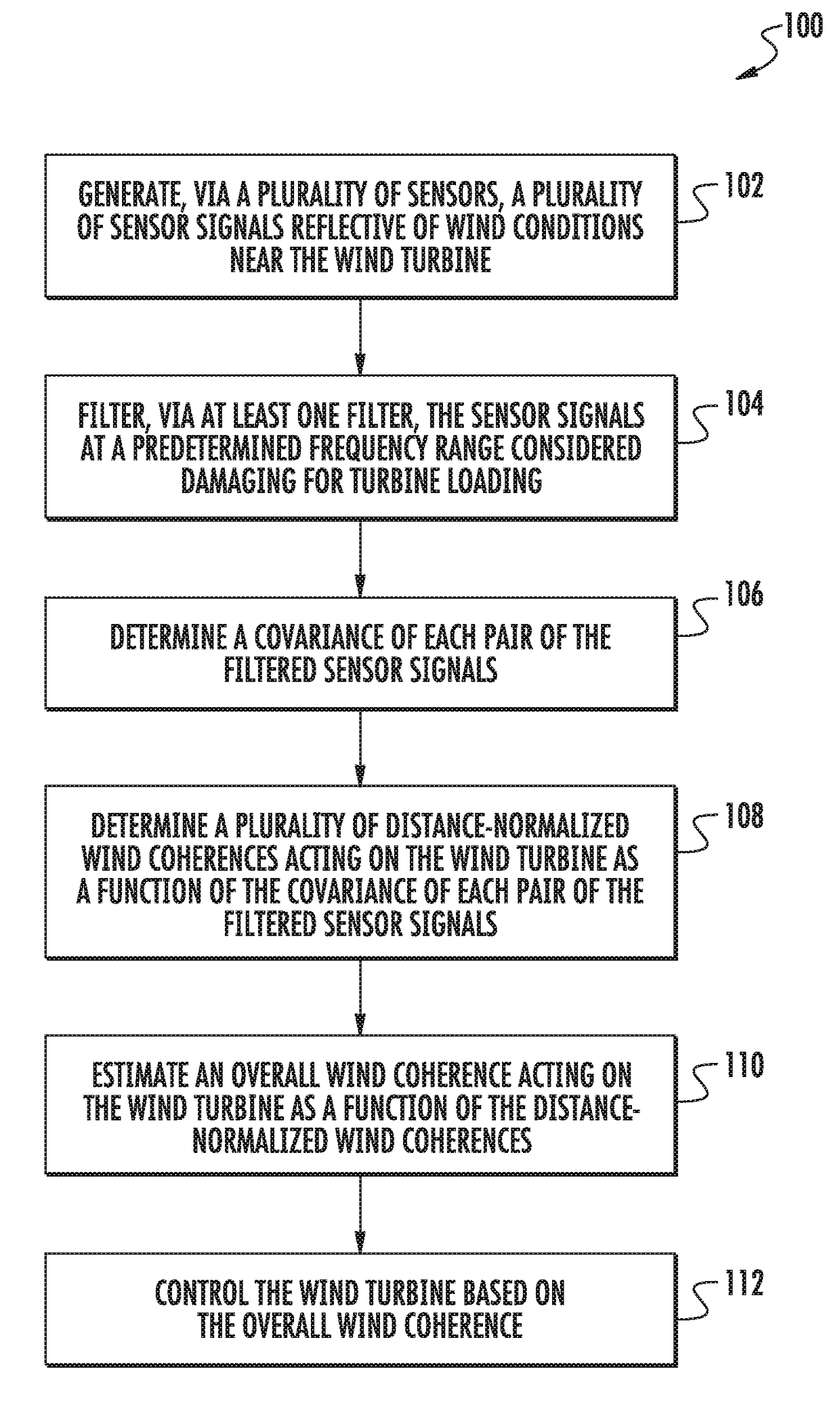
The present invention is directed to a method and system for estimating the overall wind coherence acting on a wind turbine. This is important for controlling the wind turbine in real-time to optimize its performance. The method involves generating sensor signals reflective of wind conditions near the wind turbine, filtering the sensor signals to remove damaging wind variations, and determining the distance-normalized wind coherences acting on the wind turbine as a function of the covariance of the sensor signals. The overall wind coherence is then estimated based on the distance-normalized wind coherences. The system includes a plurality of sensors and a controller with a processor for performing the filtering and determining the wind coherences. The technical effects of the invention include improved wind turbine performance and reduced maintenance costs.

Problems solved by technology

It is well known that large coherent structures in the wind cause extreme loads in wind turbines and determine the extreme design load envelope.
For wind transients at medium timescales, coherence decreases but could pose increased risk to the turbine loading due to resonance with natural frequencies and the controller tuning.
Such methods, however, involve complex calculations at multiple discrete frequencies, averaging over large time intervals, and can be time-consuming to complete.
Further, such methods are agnostic to the nature of wind transients that can worsen turbine loads.
Therefore, such methods are typically incapable of providing quick detection of large coherent structures and subsequent control action thereof.

Method used


Image

  • System and method for estimating wind coherence and controlling wind turbine based on same
  • System and method for estimating wind coherence and controlling wind turbine based on same
  • System and method for estimating wind coherence and controlling wind turbine based on same

Examples


Embodiment Construction

[0024]Reference now will be made in detail to embodiments of the invention, one or more examples of which are illustrated in the drawings. Each example is provided by way of explanation of the invention, not limitation of the invention. In fact, it will be apparent to those skilled in the art that various modifications and variations can be made in the present invention without departing from the scope or spirit of the invention. For instance, features illustrated or described as part of one embodiment can be used with another embodiment to yield a still further embodiment. Thus, it is intended that the present invention covers such modifications and variations as come within the scope of the appended claims and their equivalents.

[0025]Generally, the present subject matter is directed to a system and method for estimating an overall wind coherence (i.e. rotor-average loads-relevant wind coherence) acting on a wind turbine and controlling the wind turbine based on said overall wind c...


PUM


Abstract

The present disclosure is directed to a system and method for estimating an overall wind coherence acting on a wind turbine and using same to dynamically adapt the gain or bandwidth of pitch or torque or yaw control logic within a wind turbine. The method includes generating, via sensors, a plurality of sensor signals reflective of wind conditions near the wind turbine. The method also includes filtering, via at least one filter, the sensor signals at a predetermined frequency range considered damaging for turbine sub-system loading. Thus, the method also includes estimating an overall damaging wind coherence acting on the wind turbine as a function of distance-normalized wind coherences, which themselves are derived from auto and cross-covariances of pairs of filtered signals. The distance normalization uses a model of natural coherence dissipation with distance.

Description

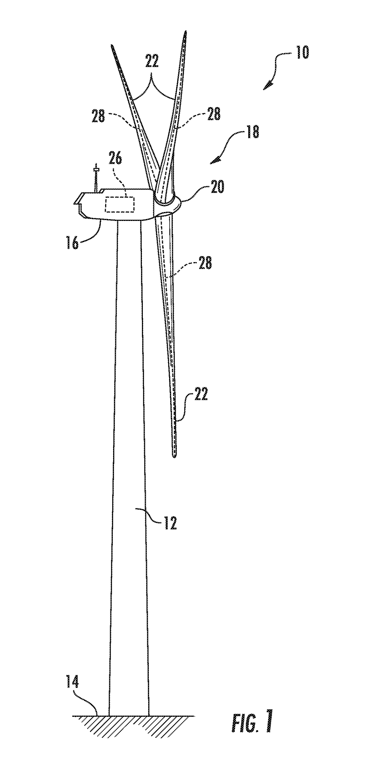
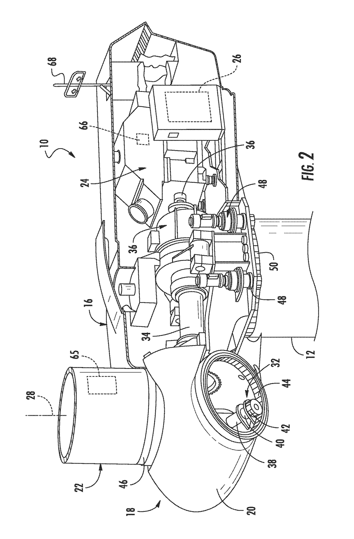
FIELD OF THE INVENTION[0001]The present invention relates generally to wind turbines, and more particularly, to systems and methods for estimating wind coherence and controlling wind turbines based on said coherence so as to prevent damage caused by extreme loads.BACKGROUND OF THE INVENTION[0002]Wind power is considered one of the cleanest, most environmentally friendly energy sources presently available, and wind turbines have gained increased attention in this regard. A modern wind turbine typically includes a tower, a generator, a gearbox, a nacelle, and a rotor. The rotor typically includes a rotatable hub having one or more rotor blades attached thereto. A pitch bearing is typically configured operably between the hub and a blade root of the rotor blade to allow for rotation about a pitch axis. The rotor blades capture kinetic energy of wind using known aerodynamic principles. The rotor blades transform the kinetic energy in the form of mechanical energy so as to turn a shaft c...

Claims


Application Information

Patent Timeline
IPC IPC(8): F03D7/04F03D9/00F03D9/25F03D7/02
CPCF03D7/046F03D7/048F03D7/0248F03D9/25F03D7/0224F03D9/005F05B2260/8211F05B2270/321F05B2270/322F03D9/257Y02E10/72
Inventor DESHPANDE, AMEET SHRIDHARMCCOY, TIMOTHY J.GUPTA, SANDEEP
Owner GENERAL ELECTRIC CO
Why Eureka
Try Eureka