Portable Lighting Apparatus

Active Publication Date: 2018-03-01
NINGBO UTEC ELECTRIC
View PDF1 Cites 12 Cited by
  • Summary
  • Abstract
  • Description
  • Claims
  • Application Information

AI Technical Summary

Benefits of technology

[0005]It is an object of the present invention is to provide a portab

Problems solved by technology

Many of the existing portable lighting apparatus suffer from several drawbacks.
First, many of them are large and bulky, and cannot be conveniently moved from one location to another location.
Second, the illumination that is delivered

Method used


Image

  • Portable Lighting Apparatus
  • Portable Lighting Apparatus
  • Portable Lighting Apparatus

Examples


Embodiment Construction

[0027]The following detailed description is of the best presently contemplated modes of carrying out the invention. This description is not to be taken in a limiting sense, but is made merely for the purpose of illustrating general principles of embodiments of the invention. The scope of the invention is best defined by the appended claims.

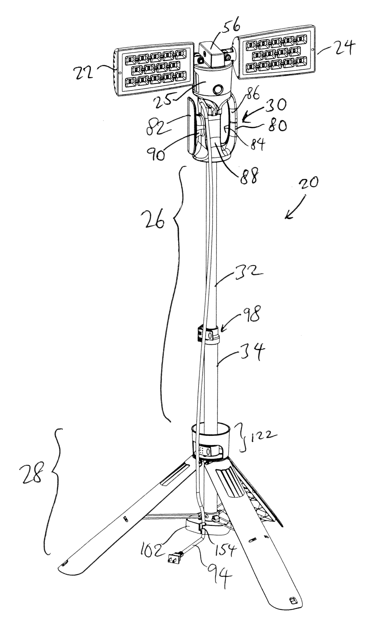
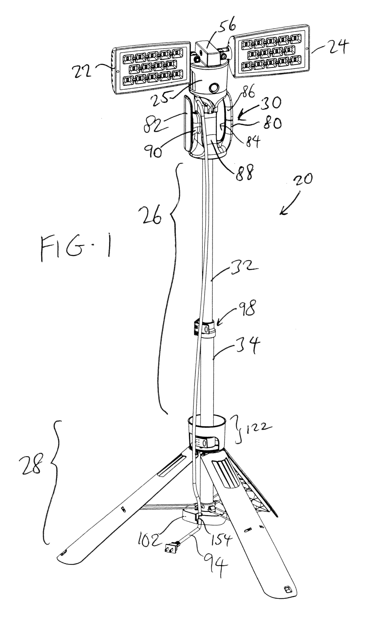
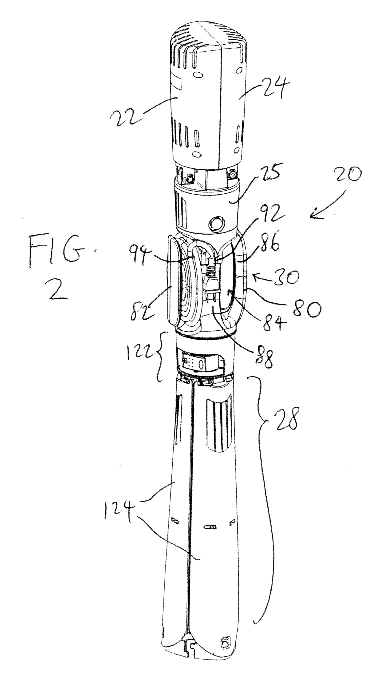
[0028]The present invention provides a portable lighting apparatus 20 which is large enough to support illumination devices 22 and 24 that can illuminate a large space, yet can be folded and collapsed into a smaller and slimmer profile so that it can be conveniently stored or transported to a different location for use. In addition, the illumination devices 22 and 24 can be adjusted so that the orientation and direction of the illumination can be adjusted without the need to move the lighting apparatus 20.

[0029]FIG. 1 illustrates the lighting apparatus 20 in an opened position during normal use. The lighting apparatus 20 has a pair of illumination...


PUM


Abstract

A lighting apparatus has an upper hub, a base, a lower hub, and a plurality of illumination devices that are pivotably supported at the upper hub, with each illumination device being pivotable up and down towards each other, as well as being rotatable. A shaft assembly has an upper end that is secured to the upper hub, and a lower end that is secured to the base. A plurality of legs is connected to the lower hub and the base for pivoting motion therebetween.

Description

BACKGROUND OF THE INVENTION1. Field of the Invention[0001]The present invention relates to a lighting apparatus, and in particular, to a portable lighting apparatus that can be used to illuminate a large area, and which can be collapsed into a smaller configuration for storage and transportation.2. Description of the Related Art[0002]There is a wide variety of lighting apparatus that are available to accommodate the many lighting needs inside homes, offices and large meeting areas or buildings. There are also lighting apparatus that are adapted for outdoor use. Some of the lighting apparatus are fixed in that they are secured to permanent locations (e.g., wall or ceiling lights), while others are portable in that they can be moved from one location to another location.[0003]Many of the existing portable lighting apparatus suffer from several drawbacks. First, many of them are large and bulky, and cannot be conveniently moved from one location to another location. Second, the illumin...

Claims


Application Information

Patent Timeline
IPC IPC(8): F21V21/14F21L14/00F21V21/26F21V21/40F21V21/22F21V23/00
CPCF21V21/145F21L14/00F21V21/26F21V21/406F21V21/22F21V23/002F21Y2115/10F21Y2105/10F21V27/02F21S6/005F21V17/007F21V17/02F21V21/06F21V21/30F21V23/001F21W2131/10
Inventor FANG, YI
Owner NINGBO UTEC ELECTRIC
Why Eureka
Try Eureka