Environmental control system

a control system and environment technology, applied in lighting and heating apparatus, heating types, instruments, etc., can solve problems such as mold and other microbial growth, and achieve the effect of limiting or preventing condensation in the controlled environment and minimizing or preventing condensation

Inactive Publication Date: 2018-03-01
CARIGNAN RICK
View PDF5 Cites 7 Cited by
  • Summary
  • Abstract
  • Description
  • Claims
  • Application Information

AI Technical Summary

Benefits of technology

[0004]In one aspect, an environmental control system is provided. The system is configured to minimize or prevent formation of condensation within the controlled environment. The system is controlled and operated by a computerized controller. A first relative humidity (RH) sensor is positioned within a control environment and is in electronic communication with the computerized controller. A first temperature sensor is also positioned within the control environment, and is in electronic communication with the computerized controller. The continued measurement of the temperature and relative humidity computes the dew point for the control environment. The system further includes a second temperature sensor that is positioned within the evaluation environment and is in electronic communication with the computerized controller. The controller is configured to receive inputs from the first humidity sensor and first and second temperature sensors. Based on these inputs, the controller may operate an air controller, such as a fan, HVAC unit, or other apparatus that is configured to move a quantity of air between the control environment and evaluation environment, and / or condition the air in a controlled environment to maintain environmental conditions to limit or prevent condensation in the controlled environment.
[0005]The Controller continually measures the dew point in a control environment and compares it against the ambient air temperature in an evaluation environment. When certain conditions are met the controller causes the activation of a motor that turns on a fan / HVAC or some other type of apparatus that can cause an exchange of air between the evaluation and the control environment thereby removing the conditions that will lead to the formation of condensation to form inside the control environment. HVAC is a dehumidification apparatus that would condition the air in the control environment and would not cause and exchange of air between environments.

Problems solved by technology

In enclosures or enclosed environments, humidity levels coupled with temperature swings can lead to condensation.
This condensation may cause substantial damage, as well as problems such as mold and other microbial growth.

Method used


Image

  • Environmental control system
  • Environmental control system
  • Environmental control system

Examples


Embodiment Construction

[0009]The detailed description set forth below in connection with the appended drawings is intended as a description of presently preferred embodiments of the invention and does not represent the only forms in which the present invention may be constructed and / or utilized. The description sets forth the functions and the sequence of steps for constructing and operating the invention in connection with the illustrated embodiments.

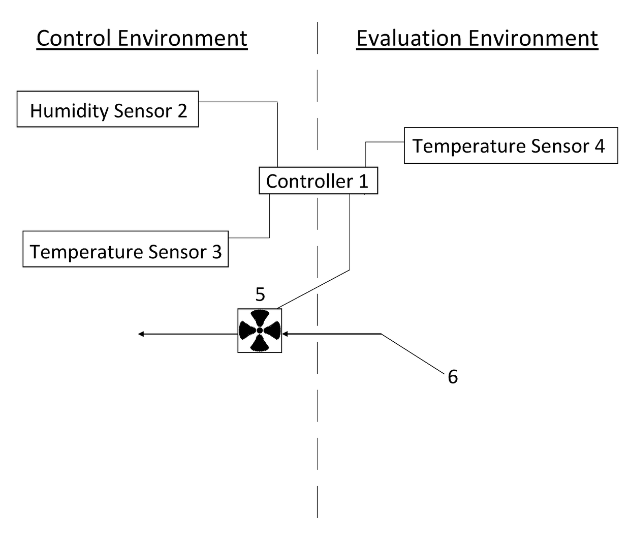
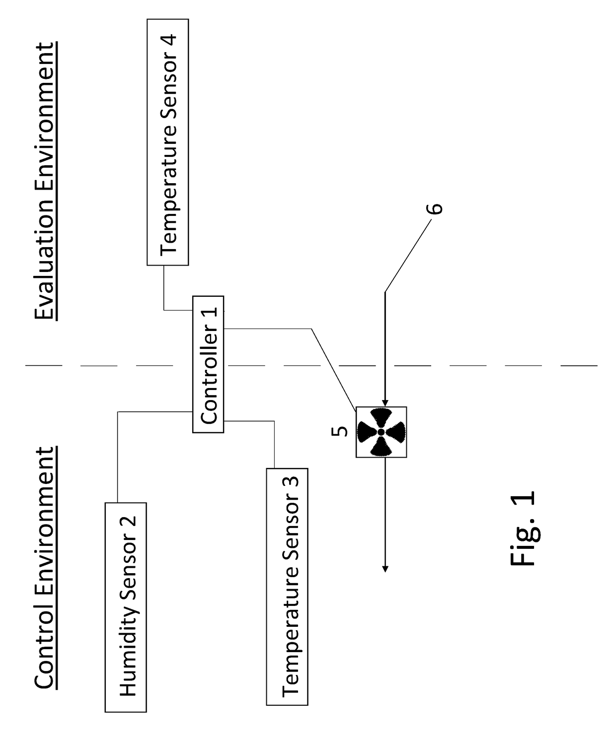
[0010]The purpose of the present invention a controller that continually monitors the atmospheric conditions in a controlled environment (i.e. inside an enclosure or enclosed area) that can lead to the formation of water or liquid condensation (i.e. either in the form of liquid water, water ice or other types of materials that can be converted from a gas into a liquid when the correct environmental conditions exist).

[0011]The control system of the present invention equalizes the atmospheric conditions between a controlled environment and an evaluation enviro...


PUM


Abstract

An environmental control system is provided. The control system is configured to minimize formation of condensation by measuring dew points and temperatures. A system controller activates an air controller or air conditioner based on these monitored parameters such as a fan to move air between a controlled environment and evaluation environment or to recondition the air inside the control environment to maintain proper conditions within the controlled environment.

Description

BACKGROUND OF THE INVENTIONField of the Invention[0001]The present invention relates generally to environmental controllers. More particularly the present invention relates to a system that maintains an enclosure environment at conditions sufficient to prevent condensation.Description of Related Art[0002]In enclosures or enclosed environments, humidity levels coupled with temperature swings can lead to condensation. Condensation may be in the form of liquid, ice, or other materials that may be converted from gas into liquid under certain environmental conditions. This condensation may cause substantial damage, as well as problems such as mold and other microbial growth. Therefore, the need exists to maintain an enclosure or enclosed area at conditions to prevent said condensation.SUMMARY OF THE INVENTION[0003]The subject matter of this application may involve, in some cases, interrelated products, alternative solutions to a particular problem, and / or a plurality of different uses of...

Claims


Application Information

Patent Timeline
Patent Type & Authority Applications(United States)
IPC IPC(8): G05D27/02F24F11/00
CPCG05D27/02F24F2011/0002F24F11/0008F24F2110/10F24F2110/12F24F2110/20G05D22/02G05D23/1931
Inventor CARIGNAN, RICK
Owner CARIGNAN RICK
Why Eureka
Try Eureka