Gate drive circuit and liquid crystal display device

a technology of liquid crystal display device and gate drive circuit, which is applied in the field of display, can solve the problems of reducing the reliability and the lifespan of the gate drive circuit, and achieve the effect of easy fluctuation

Active Publication Date: 2018-03-01
TCL CHINA STAR OPTOELECTRONICS TECH CO LTD
View PDF3 Cites 6 Cited by
  • Summary
  • Abstract
  • Description
  • Claims
  • Application Information

AI Technical Summary

Benefits of technology

[0005]An objective of the present invention is to provide a gate drive circuit and a liquid crystal display device to solve the technical problem that the pull-down point is easily fluctuated when the pull-down point is pulled down in the prior art.

Problems solved by technology

As a result, the reliability and the lifespan of the gate drive circuit are decreased.

Method used


Image

  • Gate drive circuit and liquid crystal display device
  • Gate drive circuit and liquid crystal display device
  • Gate drive circuit and liquid crystal display device

Examples


Embodiment Construction

[0031]The following embodiments are referring to the accompanying drawings for exemplifying specific implementable embodiments of the present invention. Furthermore, directional terms described by the present invention, such as upper, lower, front, back, left, right, inner, outer, side and etc., are only directions by referring to the accompanying drawings, and thus the used directional terms are used to describe and understand the present invention, but the present invention is not limited thereto.

[0032]In the drawings, structure-like elements are labeled with like reference numerals.

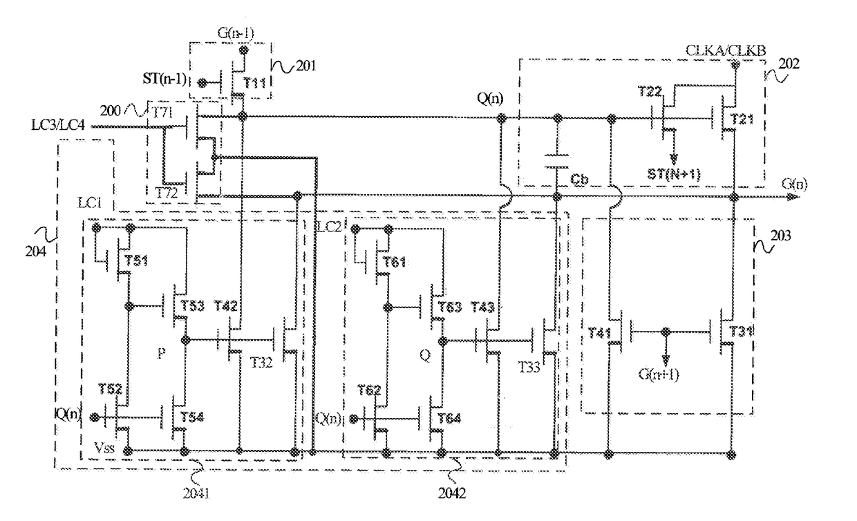
[0033]Please refer to FIG. 2. FIG. 2 is a structure of an N-th stage gate drive circuit in accordance with the present invention.

[0034]The gate drive circuit in accordance with the present invention comprises multiple stages of gate drive units connected in series. The N-th stage gate drive unit shown in FIG. 2 comprises a first (N−1)th stage signal input terminal, a second (N−1)th stage signal input t...


PUM


Abstract

The present invention provides a gate drive circuit and a liquid crystal display device. The gate drive circuit includes multiple stages of gate drive units connected in series. An N-th stage gate drive unit includes a pull-up control module, a pull-up module, a first pull-down module, a pull-down control module, and a second pull-down module. The second pull-down module includes a first thin film transistor and a second thin film transistor.

Description

BACKGROUND OF THE INVENTIONField of Invention[0001]The present invention relates to a display field, and more particularly to a gate drive circuit and a liquid crystal display device.Description of Prior Art[0002]A gate drive circuit is referred to as a GOA (Gate Driver on Array) circuit which utilizes a conventional array manufacturing process of a thin film transistor liquid crystal display device to manufacture a gate scan drive signal circuit on an array substrate, thereby implementing a drive method in which gates are scanned row by row.[0003]A structure of a conventional N-th stage GOA unit shown in FIG. 1 mainly comprises a pull-up control module101, a pull-up module 102, a pull-down module 103, and a pull-down control module 104. G(n−1) is a signal which is inputted to a first (N−1)th stage signal input terminal. ST(n−1) is a signal which is inputted to a second (N−1)th stage signal input terminal. G(n+1) is a signal which is inputted to an (N+1)th stage signal input termina...

Claims


Application Information

Patent Timeline
Patent Type & Authority Applications(United States)
IPC IPC(8): G09G3/36
CPCG09G3/3677G09G2310/08G09G2310/0289G09G2320/043G09G2330/021
Inventor XU, XIANGYANG
Owner TCL CHINA STAR OPTOELECTRONICS TECH CO LTD
Why Eureka
Try Eureka