Method of manufacturing software controlled antenna

a software control and antenna technology, applied in the direction of resonant antennas, substantially flat resonant elements, other domestic articles, etc., can solve the problems of reducing the quality of transmission and reception in that environment, difficult to design and place such antennas within the device, and restricted placement of antennas

Active Publication Date: 2018-03-01
WAFER LLC +1
View PDF0 Cites 21 Cited by
  • Summary
  • Abstract
  • Description
  • Claims
  • Application Information

AI Technical Summary

Benefits of technology

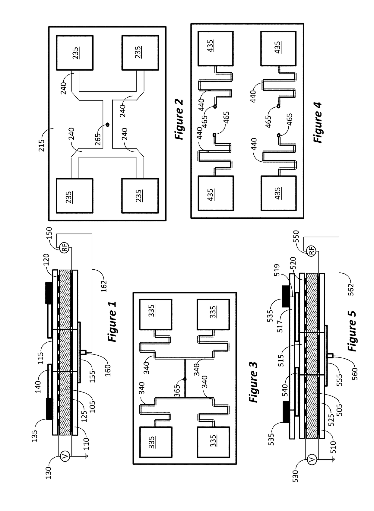
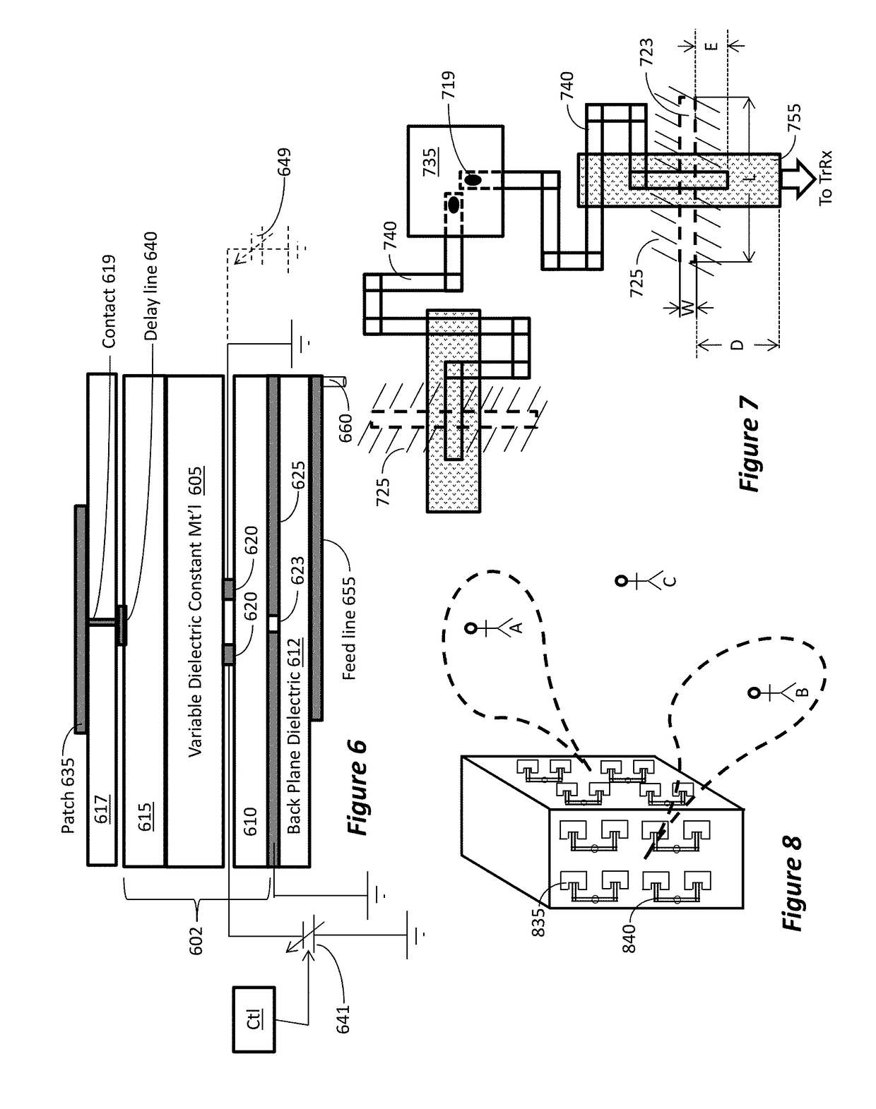
[0008]The sandwich of layers may be a standard flat panel display or a multilayer dielectric substrates, wherein images depicted on the flat panel display are software controlled with a program designed to change the dielectric constant, thus providing scanning and tuning ability to the array. That is, different images are programmed according to specifically desired change in the dielectric property of different pixels under different patches or feed-lines of the array, thereby controlling the frequency and / or directivity of the array, and the direction of the radiation beam of the antenna (i.e., enabling electronic steering of the antenna).

Problems solved by technology

Also, when several omni-directional antennas operate simultaneously, e.g., multiple devices in an Internet café, the various transmissions may interfere with each other, or at least reduce the quality of transmission and reception in that environment.
Consequently placement of the antenna is very restricted.
Since the real estate area on mobile devices is at a high premium, it is very difficult to design and place such antennas within the device.

Method used


Image

  • Method of manufacturing software controlled antenna
  • Method of manufacturing software controlled antenna
  • Method of manufacturing software controlled antenna

Examples


Embodiment Construction

[0030]The detailed description starts with the description of the antenna, and then proceeds to the description of the method for making the antenna. Embodiments of the inventive antenna will now be described with reference to the drawings. Different embodiments or their combinations may be used for different applications or to achieve different benefits. Depending on the outcome sought to be achieved, different features disclosed herein may be utilized partially or to their fullest, alone or in combination with other features, balancing advantages with requirements and constraints. Therefore, certain benefits will be highlighted with reference to different embodiments, but are not limited to the disclosed embodiments. That is, the features disclosed herein are not limited to the embodiment within which they are described, but may be “mixed and matched” with other features and incorporated in other embodiments.

[0031]As for the antenna itself, the following aspects are noted. Accordi...


PUM

PropertyMeasurementUnit
dielectric constantaaaaaaaaaa

Abstract

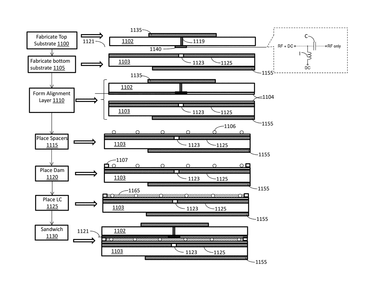
An antenna is fabricated by: passing first dielectric strip through metallization station and forming a plurality of radiating patches on top surface of the first dielectric strip and a plurality of delay lines on bottom surface of the first dielectric strip; passing a second dielectric strip through metallization station and forming a common ground on top surface of the second dielectric strip and a plurality of feed lines on bottom surface of the second dielectric strip; passing the first and second dielectric strips through an alignment material deposition station and depositing an alignment layer; depositing spacers; depositing liquid crystal material over the top surface of the second dielectric strip or over the bottom surface of the first dielectric strip; adhering the first and second dielectric strips together to form a multi-layer strip; cutting the multi-layer strip into individual antennas.

Description

RELATED APPLICATIONS[0001]This application is a continuation-in-part of U.S. patent application Ser. No. 15 / 667,584, filed on Aug. 2, 2017, and claims priority benefit from U.S. Provisional Application No. 62 / 382,489, filed on Sep. 1, 2016, U.S. Provisional Application No. 62 / 382,506, filed on Sep. 1, 2016, and U.S. Provisional Application No. 62 / 431,393, filed on Dec. 7, 2016, and is also related to U.S. patent application Ser. No. 15 / 421,388, filed on Jan. 31, 2017, and U.S. patent application Ser. No. 15 / 654,643, filed on Jul. 19, 2017, the disclosures of all of which are incorporated herein by reference in their entireties.BACKGROUND1. Field[0002]This disclosure relates to method of manufacturing antennas having an array of radiating elements forming a directionally controlled radiation beam. The parameters of radiation of the radiating elements can be controlled by software.2. Related Art[0003]Much of today's communication is done wirelessly, or at least part of the path is wir...

Claims


Application Information

Patent Timeline
Patent Type & Authority Applications(United States)
IPC IPC(8): H01Q21/00H01Q9/04B32B37/14B32B38/00
CPCH01Q21/0087H01Q9/0407H01Q9/045B32B37/14B32B38/0008B32B2457/00B32B2038/0092H01Q1/2291H01Q3/36H01Q21/0075H01Q21/065H01Q21/205H01Q25/00Y10T29/49016
Inventor HAZIZA, DEDI DAVID
Owner WAFER LLC
Why Eureka
Try Eureka