
Modular, Retractable, Solar Array and Methods for Manufacturing Same

Inactive Publication Date: 2019-01-03
ALBERTELLA ROBERTO
View PDF0 Cites 9 Cited by
  • Summary
  • Abstract
  • Description
  • Claims
  • Application Information

AI Technical Summary

Benefits of technology

This patent describes a new type of solar panel system that is portable, easy to install and take down, and can be stored easily. The system uses a supporting structure that allows the solar panels to be easily put in and removed from service. This new technology simplifies and accelerates solar deployments, making it easier to install and move around. This makes solar power more accessible, affordable, and easy to deploy in places where it wasn't previously possible.

Problems solved by technology

Despite continuous advances in PV technology and the sector's record growth, there are numerous situations where today's traditional PV installation projects are unfeasible.
Obstacles include sites with time or land constraints, situations when the need for energy is immediate or its duration unknown, or when upfront capital requirements are too high.
This is no easy task because it typically takes many years for a roof-mounted solar installation to pay for itself.
Also, roof mounted systems are hard to access, and there have been many reports of safety concerns.
Another drawback associated with installation of PV panels is that it is expensive, not entirely due to the cost of panels, which have significantly decreased in recent years, but rather due to associated hardware and soft costs that are required for installation, such as labor associated with system design and installation.
However, the weight of the solar panels made it difficult to create a system having more than just a few panels that could actually deploy and retract.
Not only was the extension / retraction mechanism in FIGS. 1a and 1b insufficient to extend or retract the panels so connected but the weight of the extended structure was too great to permit the actual desired number of panel to be included in a single configuration.

Method used


Image

  • Modular, Retractable, Solar Array and Methods for Manufacturing Same
  • Modular, Retractable, Solar Array and Methods for Manufacturing Same
  • Modular, Retractable, Solar Array and Methods for Manufacturing Same

Examples


Embodiment Construction

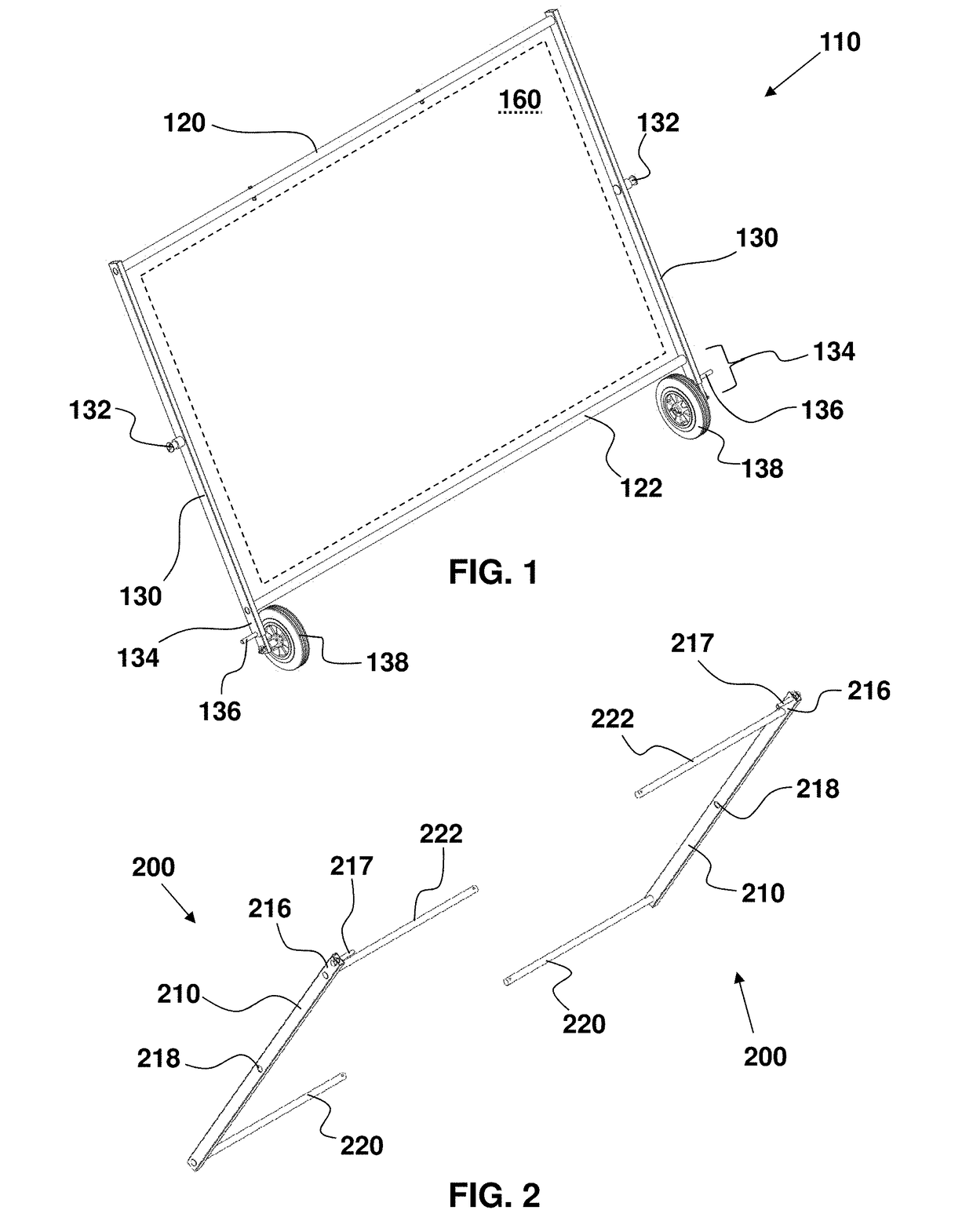
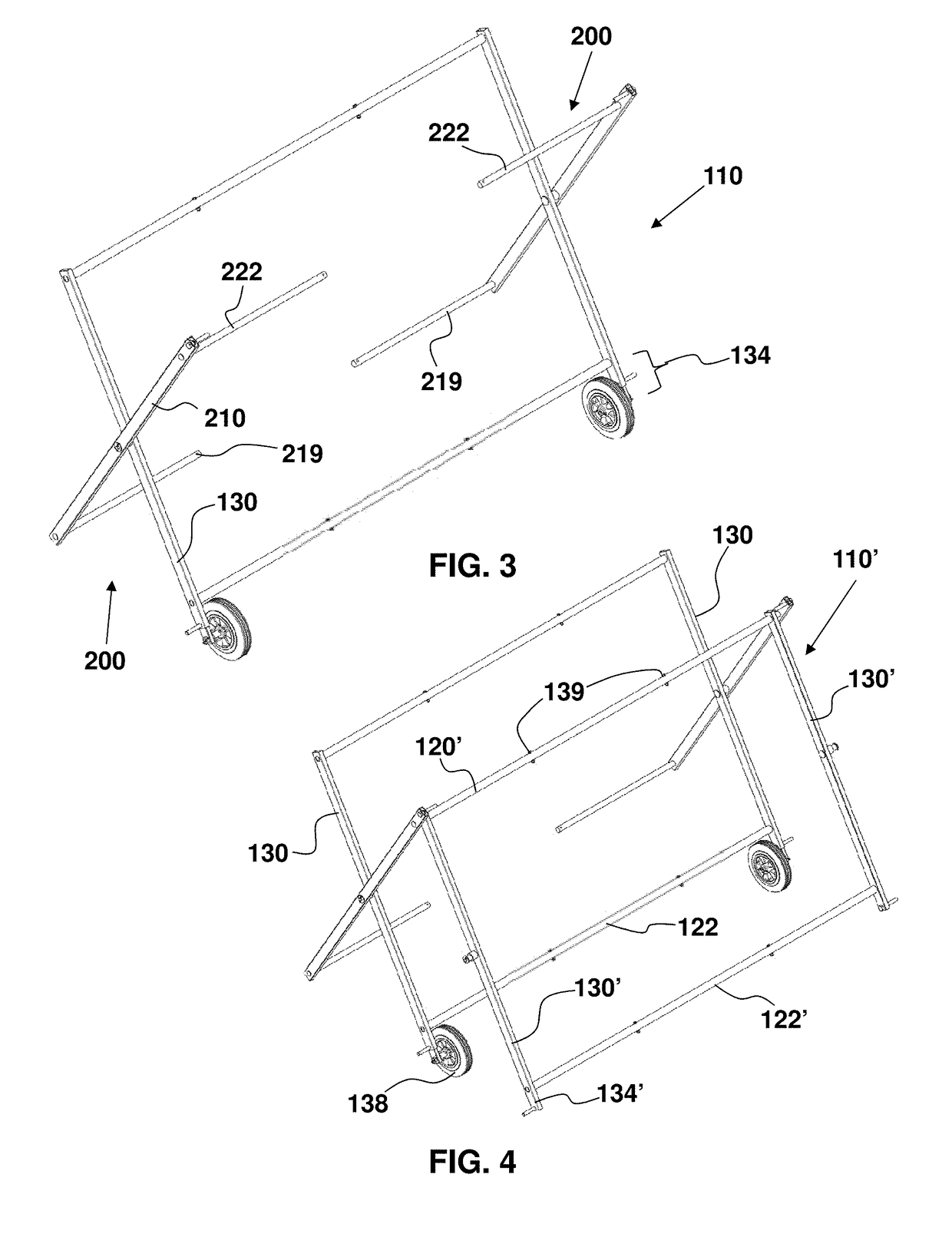
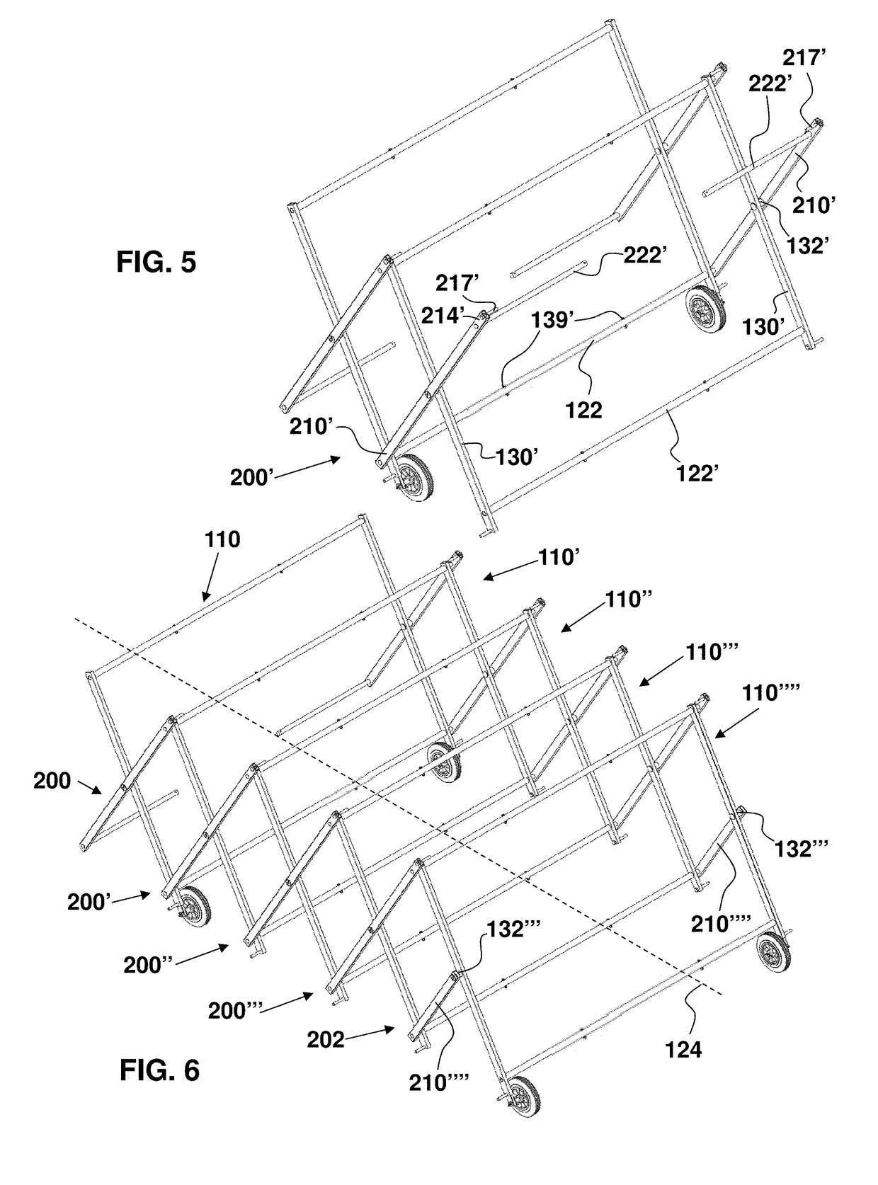
[0089]As required, detailed embodiments of the systems, apparatuses, and methods are disclosed herein; however, it is to be understood that the disclosed embodiments are merely exemplary of the systems, apparatuses, and methods, which can be embodied in various forms. Therefore, specific structural and functional details disclosed herein are not to be interpreted as limiting, but merely as a basis for the claims and as a representative basis for teaching one skilled in the art to variously employ the systems, apparatuses, and methods in virtually any appropriately detailed structure. Further, the terms and phrases used herein are not intended to be limiting; but rather, to provide an understandable description of the systems, apparatuses, and methods. While the specification concludes with claims defining the features of the systems, apparatuses, and methods that are regarded as novel, it is believed that the systems, apparatuses, and methods will be better understood from a conside...


PUM


Abstract

A portable, retractable, solar racking system comprises a modular set of solar panel frames, each solar panel frame comprising a solar panel, a plurality of arms, and a plurality of struts, the arms and the struts forming a structure to which the solar panel is secured, a pivoting connector assembly mechanically connecting one of the solar panel frames to another one of the solar panel frames to form a solar panel array having a longitudinal extent, the pivoting connector assembly of the solar panel frames configured to collapse the solar panel array along the longitudinal extent into a storage position and to expand the solar panel array along the longitudinal extent into an extended position in which each solar panel is tilted from vertical to an angle away therefrom, and the solar panel array comprising sets of wheels permitting the solar panel array to roll upon ground.

Description

CROSS-REFERENCE TO RELATED APPLICATIONS[0001]This application claims the priority, under 35 U.S.C. § 119, of copending U.S. Provisional Patent Application Nos. 62 / 526,131, filed Jun. 28, 2017, and 62 / 628,666, filed Feb. 9, 2018, the prior applications are herewith incorporated by reference herein in their entireties.STATEMENT REGARDING FEDERALLY SPONSORED RESEARCH OR DEVELOPMENT[0002]Not ApplicableFIELD OF THE INVENTION[0003]The present systems, apparatuses, and methods lie in the field of solar, photovoltaic, power generation. The present disclosure relates to portable, modular, retractable, solar panel arrays, solar panel systems, and methods for manufacturing same.BACKGROUND OF THE INVENTION[0004]The system power of a photovoltaic system depends on the number of photovoltaic panels that are used. Therefore, a usably functional photovoltaic (PV) system requires an expansive area. But, those areas are valuable for other uses and can be exploited for those uses if the photovoltaic s...

Claims


Application Information

Patent Timeline
IPC IPC(8): H02S30/20H02S20/30H02S30/10
CPCH02S30/20H02S20/30H02S30/10Y02E10/50
Inventor ALBERTELLA, ROBERTO
Owner ALBERTELLA ROBERTO
Learn More