

Methods and Associated Devices and Systems for Enhanced 2D and 3D Vision
- Summary
- Abstract
- Description
- Claims
- Application Information
AI Technical Summary
Benefits of technology
Problems solved by technology
Method used
Image

Examples
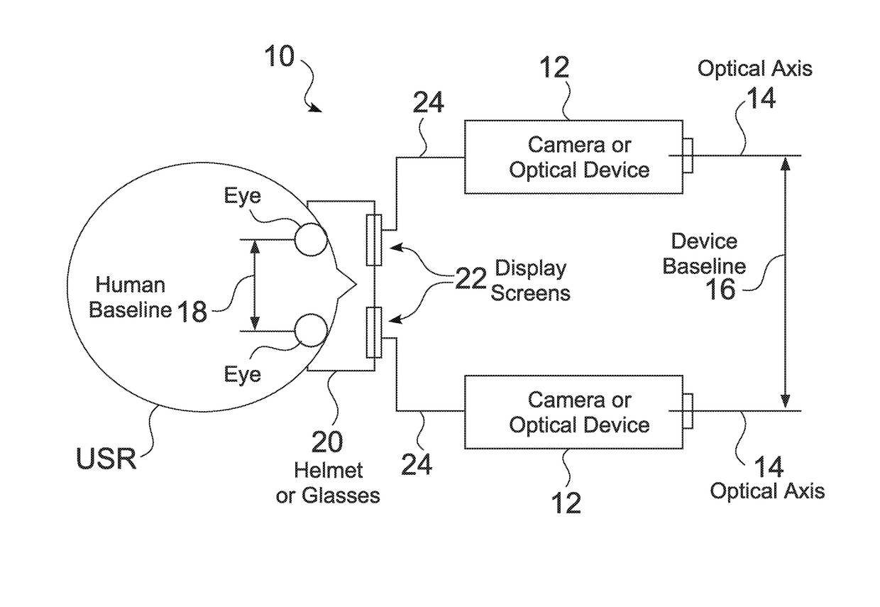
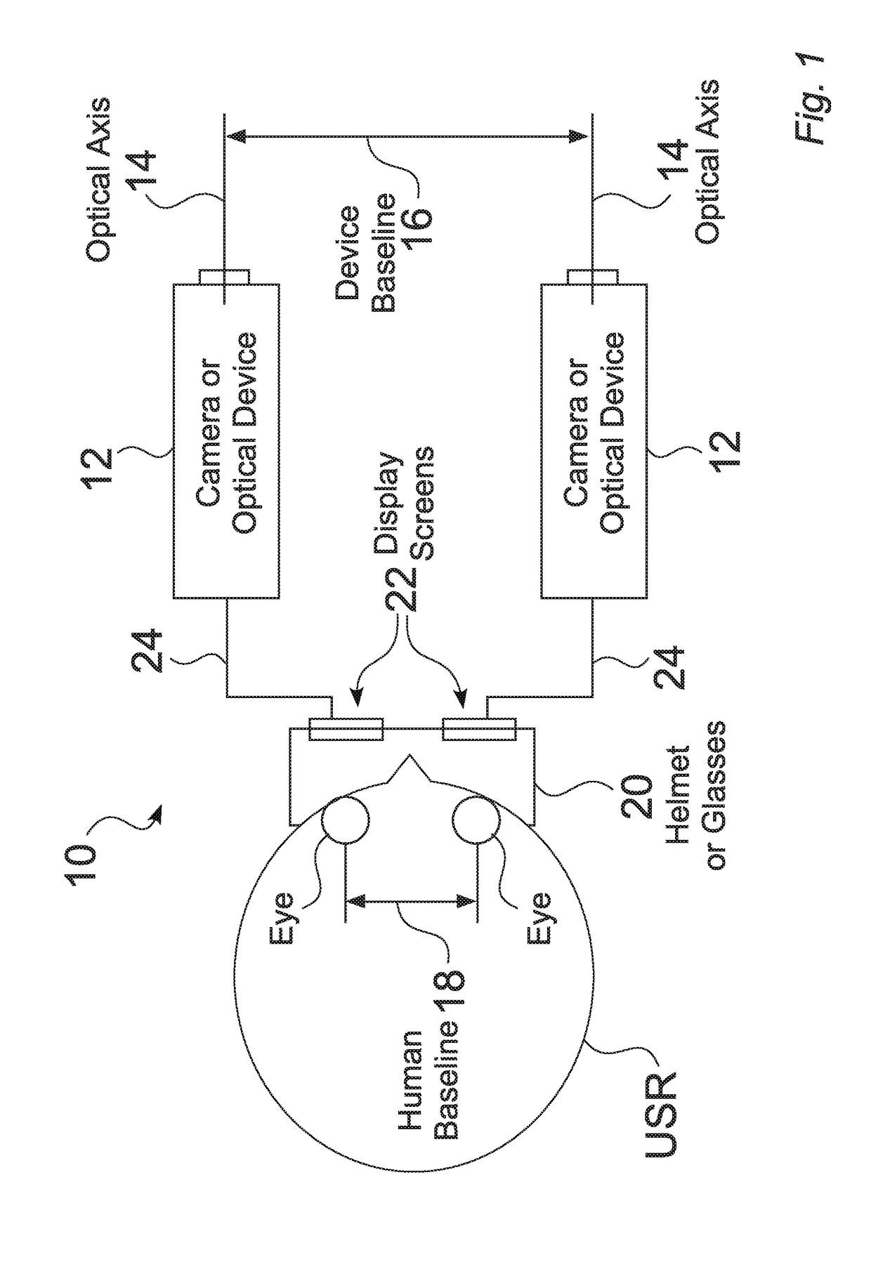
embodiment 10
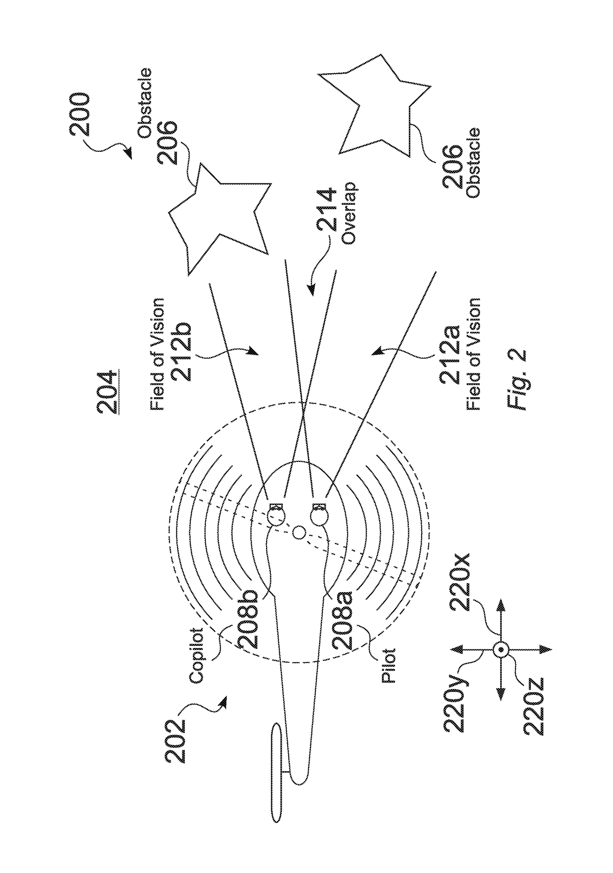
[0043]Stereoptic views produced 412 by the system 10 can be enhanced by combining images obtained from at least two independent or independently operated cameras 12. In an illustrative system embodiment 10, such as shown in FIG. 1, FIG. 2 and FIG. 3, two independent cameras 12 are mounted on the heads of a helicopter pilot 208a and a co-pilot 208b. In some embodiments, the cameras 12 can be enabled for any of night vision, thermal vision, or other purposes. Because the cameras 12 are mounted to the helmets, e.g., 1002 (FIG. 23), the pilot 208a and co-pilot 208b can select what they wish to view, i.e., the scene 212, e.g., 212a and 212b, by moving their heads. At any given time, the pilot 208a and co-pilot 208b may be looking at different scenes 212, but in many instances there is a significant overlap 214 in the scenes 212.
[0044]By utilizing position sensors 302 (FIG. 3) mounted in the helmet 1002 or the camera 12, the system 10 is able to determine 404 (FIG. 4) when the scenes 212 ...
embodiment 700
[0074]In the illustrative embodiment 700 seen in FIG. 11, a beamsplitter 710 that is enabled to reflect ultraviolet light and transmit visible light is positioned 742 between the NVG output 704 and the user's eye. A steerable laser 706 in the ultraviolet range is aimed 744 at the beamsplitter 710, such that its beam 708 is reflected 712 towards the phosphor screen 714. When the beam 712 hits the screen 714, its energy causes photons to be emitted 718 towards the user's eye. Thus, a steerable UV beam 708 can paint symbology, e.g., 608, 610 (FIGS. 7-10) onto the phosphor screen 714, which the user will see overlaid 746 on the amplified analog image 704.
[0075]In an illustrative embodiment a method comprises positioning a beamsplitter 710 that is enabled to reflect light 708 outside the visible spectrum, and to transmit visible light 704 between the output of an image intensifier 702 associated with night vision goggles (NVG) and a phosphor screen 714. The illustrative method aims a ste...
embodiment 900
[0084]In the embodiment 900 shown in FIG. 17, a sensor 906 is oriented so that it looks forward from the vehicle 902 on a plane parallel to the ground. A periscope like device 904 is then placed inline with the night vision system 900. The periscope 904 is affixed to a pivot 905 on the vertical plane along the z-axis of the night vision system. As a result, in some embodiments, the periscope 904 can rotate 908 so that it provides a view from both a higher and lower perspective. In some embodiments, the periscope 904 can also be rotated to provide a right and left perspective.
[0085]In some embodiments, the periscope 904 constantly rotates, e.g., at a rate of at least 30 times per second. During this rotation, the night vision system 900 can constantly record images. The video captured by the night vision system 900 can be transmitted 912 back to the remote operator RO. If this feed were to be viewed without further processing, it would display the view directly in front of the remote...
PUM
 Abstract
Description
Claims
Application Information