Ionization air purification system for the passenger cabin of a vehicle

a technology for air purification systems and passenger cabins, which is applied in the direction of electric supply techniques, separation processes, transportation and packaging, etc., can solve the problems of no commercially available systems, adverse effects on the health of passengers, and no system specially suitable for such use, so as to minimize the ability of free electrons and minimize the production of ozone

Active Publication Date: 2018-03-08
CLEAN AIR GROUP
View PDF24 Cites 12 Cited by
  • Summary
  • Abstract
  • Description
  • Claims
  • Application Information

AI Technical Summary

Benefits of technology

[0011]In one embodiment, an ionization air purification system for the passenger cabin of a vehicle is disclosed. The system includes an ionization device for purifying the air prior to entering into the passenger cabin of the vehicle while minimizing the production of ozone as a by-product. The system includes a control device having a potentiometer for modifying the degree of ionization by modifying the energy levels applied to the ionization device or ionization source proportional to the change in air flow dynamics or air quality. The air ionization device incorporates a glass or fiberglass dielectric member positioned between an anode and a cathode. The air ionization device is configured to produce balanced quantities of both positive ions and negative ions occurring alternately so that the ions are dispersed in an alternate fashion to avoid re-combination and opportunity to form ozone. The air ionization device is configured to operate at a voltage in the range of 1,350-4,500 VAC (volts alternating current) to minimize the ability of free electrons to convert dioxygen (O2) to ozone (O3).

Problems solved by technology

It is believed that there are no commercially available systems that address problems unique to passenger vehicles which include variable air flow parameters which are subject to significant variation in air flow and the significant, but often varying changes in air quality, particularly with regard to gaseous pollutants which are often encountered, all of which can have significant impact on the efficiency and efficacy of the ionization system.
Indeed there is much discussion in literature that the constant recirculation of unpurified air within air craft has had adverse affects upon the health of passengers as they are constantly exposed to the same recirculated air.
Although the potential benefits of an ionization system in the field of transportation would have many benefits, to date no one has created a system particularly suitable for such use.

Method used


Image

  • Ionization air purification system for the passenger cabin of a vehicle
  • Ionization air purification system for the passenger cabin of a vehicle
  • Ionization air purification system for the passenger cabin of a vehicle

Examples


first embodiment

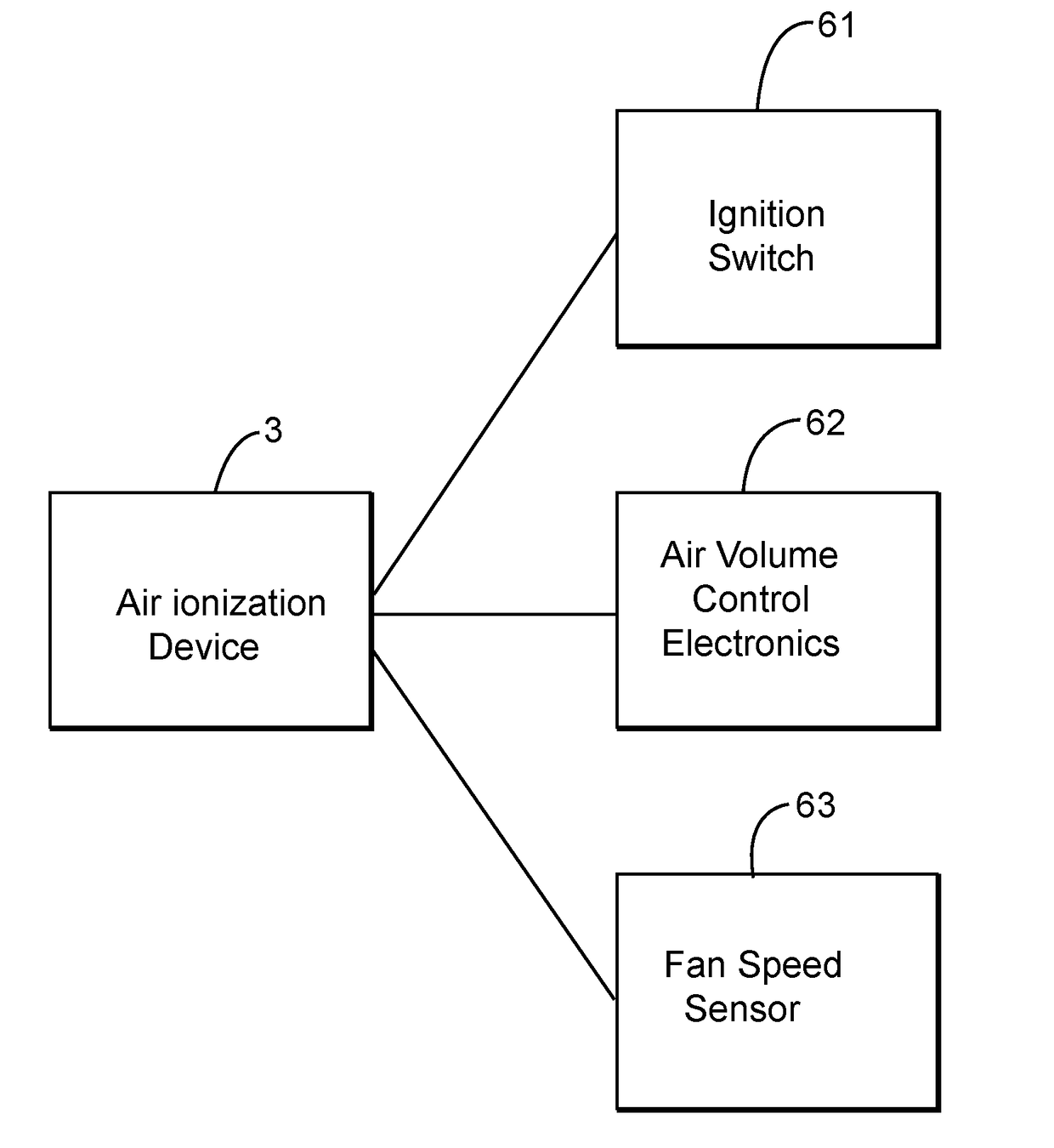
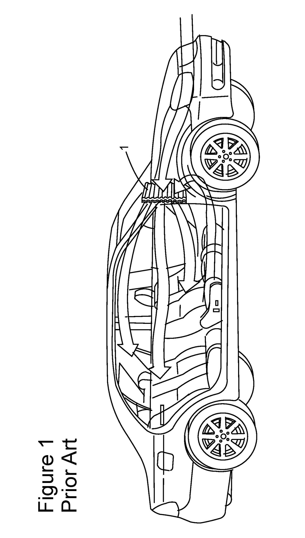
[0033]FIG. 5A illustrates the present invention, as implemented into the engine compartment of an automobile. As illustrated, a plenum chamber 4 is positioned within the engine compartment of the automobile, and is shown with the cover panel (not shown) removed. An air ionization device 3 having a tubular dielectric member is fixedly mounted to a sidewall of the plenum chamber 4 so as to extend into the air flow from the intake, which in the case of an automobile (as shown in FIG. 1) generally is located along the base of the windshield as that location tends to reduce the extent of the intake of pollution in the outside air. The cabin air filter 1 is shown positioned against a sidewall of the plenum chamber 4 towards the passenger cabin and a filter housing 2.

[0034]As further illustrated in FIG. 5A, the air ionization is performed using an ionization device 3 having a tubular dielectric member, but it is also contemplated that the ionization may be accomplished through other known ...

second embodiment

[0035]As illustrated in FIG. 5B, the invention is illustrated wherein the ionization device 400 has a planar dielectric member 300. Importantly, the ionization device of the present invention provides a sufficient level of ionization to effectively address the contaminants, while minimizing the production of ozone, O3, as a by-product. As illustrated, the ionization device 400 is in turn secured via a plurality of stanchions 420, 430, 440 that are mounted to a baseplate on enclosure 410 that is in turn secured to a sidewall of the plenum chamber 4 and is electrically coupled generally via hard wiring to the 12 volt system that operates in the vehicle. A control device modifies the degree of ionization by modifying the energy levels applied to the ionization tube or ionization source proportional to the change in air flow dynamics or air quality. It is preferred that planar dielectric member 300 be mounted such that it is substantially parallel to the direction of airflow to provide ...


PUM

PropertyMeasurementUnit
surface areaaaaaaaaaaa
voltageaaaaaaaaaa
dielectricaaaaaaaaaa

Abstract

An ionization air purification system for the passenger cabin of vehicles, which modifies the degree of ionization by modifying the energy levels applied to an air ionization device having a tubular dielectric member or a planar dielectric member or ionization source proportional to the change in air flow dynamics and air quality. In one embodiment, an ionization air purification system for the passenger cabin of a vehicle is disclosed. The system includes an ionization device for purifying the air prior to entering into the passenger cabin of the vehicle while minimizing the production of ozone as a by-product; and means for modifying the degree of ionization by modifying the energy levels applied to the ionization tube or ionization source proportional to the change in air flow dynamics or air quality.

Description

CROSS REFERENCE TO RELATED APPLICATION[0001]This application is a continuation-in-part of U.S. application Ser. No. 14 / 385,346, filed Sep. 15, 2014, which is a national phase of PCT Application No. PCT / US2013 / 032163, filed Mar. 15, 2013, which claims the benefit of U.S. Provisional Application No. 61 / 611,676, filed Mar. 16, 2012, all of which are hereby incorporated by reference.FIELD OF THE INVENTION[0002]The present invention relates to the use of air purification ionization systems in the field of transportation including, without limitation, cars, buses, trains, airplanes, trucks and other vehicles by which people and / or animals travel.BACKGROUND OF THE INVENTION[0003]Systems that employ ionization as a means for removing contaminants, both solid and gaseous from an air stream are known. One of the most popular uses of the technology is in products offered by ATMOSAIR™, both stand alone systems such as towers as well as systems that are installed within HVAC systems in homes and...

Claims


Application Information

Patent Timeline
Patent Type & Authority Applications(United States)
IPC IPC(8): B03C3/68B60H3/00B60H3/06B03C3/41B01D46/00A61L9/22
CPCB03C3/68B60H3/0078B60H3/0633B03C3/41B01D46/0078A61L9/22B03C2201/04B03C2201/30A61L2209/11B01D46/0028B60H1/00371H01T23/00A61L2209/111A61L2209/14A61L2209/16A61L2209/21B64D2013/067B61D27/00B64D13/00B01D46/785
Inventor ABATE, ANTHONY M.GURMAN, HAL ROSS
Owner CLEAN AIR GROUP
Why Eureka
Try Eureka