Two pressure cooling of turbine airfoils

a technology of turbine airfoil and cooling system, which is applied in the direction of blade accessories, engines/engines, blade accessories, etc., can solve the problems of airfoil damage or failure, and the cooling system of typical airfoil may be deficien

Inactive Publication Date: 2018-03-08
SIEMENS ENERGY INC
View PDF5 Cites 3 Cited by
  • Summary
  • Abstract
  • Description
  • Claims
  • Application Information

AI Technical Summary

Benefits of technology

[0004]An airfoil cooling system for a gas turbine engine is disclosed. The airfoil cooling system may be formed from at least a first cooling fluid supply system in fluid communication with a first portion of a compressor, and a second cooling fluid supply system in fluid communication with a second portion of the compressor. The first cooling fluid supply system may be configured to supply cooling fluids at a first pressure from the first portion of the compressor to one or more airfoils of a first row of airfoils arranged circumferentially around a rotor assembly of the gas turbine engine, and the second cooling fluid supply system may be configured to supply cooling fluids at a second pressure from the second portion of the compressor to the one or more airfoils of the first row of airfoils. Additionally, the second pressure may be lower than the first pressure. As such, each of the one or more airfoils may be cooled by cooling fluids at two different pressures. In particular embodiments, this may allow the airfoils to be cooled, while lowering the cost to the turbine engine for providing such cooling. For example, the cooling fluids at the second pressure may be less expensive to the turbine engine because they may undergo less compression at the compressor of the turbine engine. Additionally, this may further allow the airfoils to be more efficiently cooled, while still preventing hot gas ingestion into each of the airfoils. For example, an airfoil may include a pressure side cooling system, a suction side cooling system, and one or more chord-wise ribs (or other barrier) positioned in-between the pressure side cooling system and the suction side cooling system. Cooling fluids at the first pressure (which may be higher than the second pressure) may be supplied to the pressure side cooling system of the airfoil, thereby preventing the higher pressure fluids outside of the pressure side of the airfoil from being ingested into the airfoil, in particular embodiments. Additionally, cooling fluids at the second pressure (which may be lower than the first pressure) may be supplied to the suction side cooling system of the airfoil, in particular embodiments.

Problems solved by technology

This positioning may subject the airfoils to temperatures that can cause heat-related damage or failure in the airfoils.
This typical airfoil cooling system, however, may be deficient and / or may be ready for improvement.

Method used


Image

  • Two pressure cooling of turbine airfoils
  • Two pressure cooling of turbine airfoils
  • Two pressure cooling of turbine airfoils

Examples


Embodiment Construction

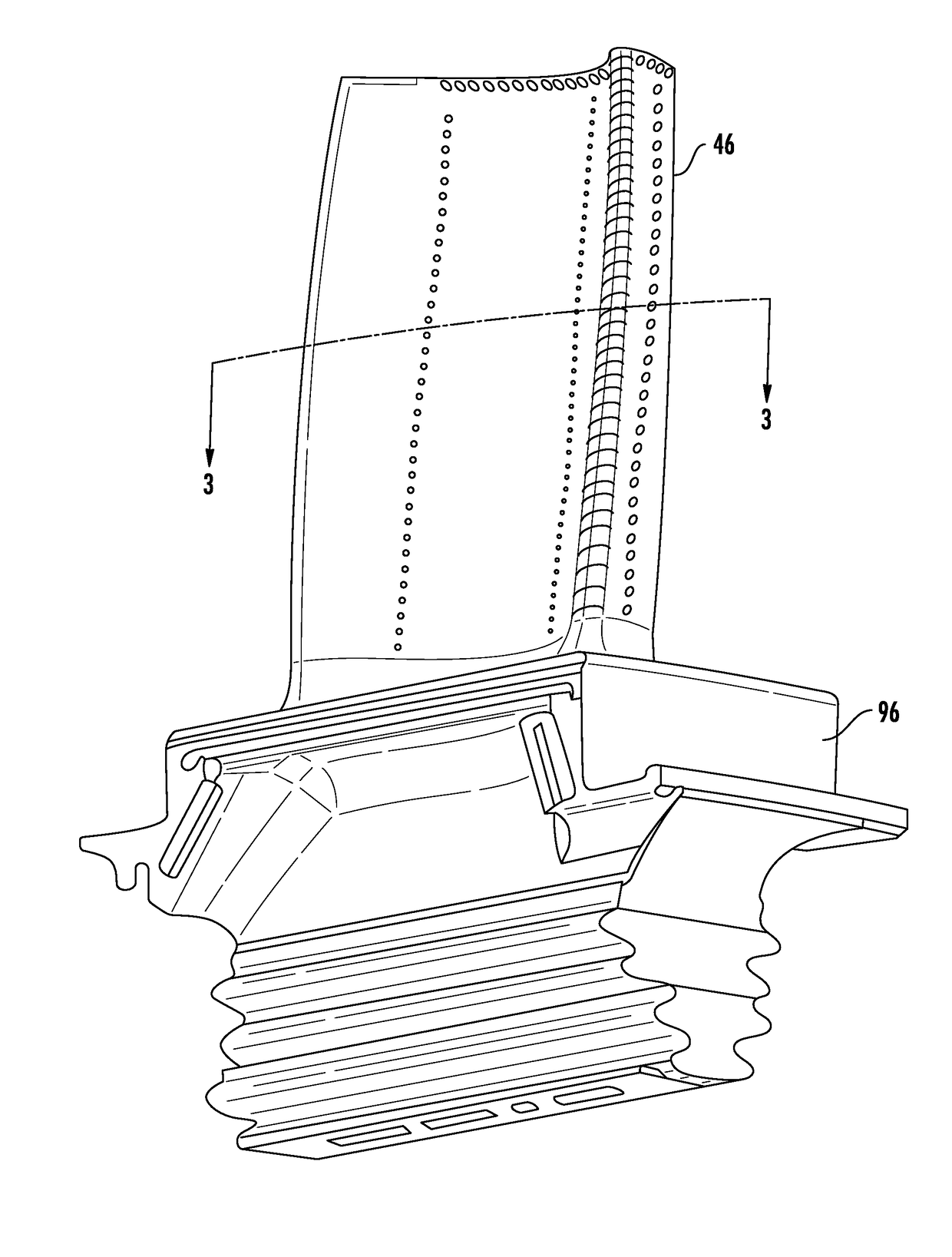
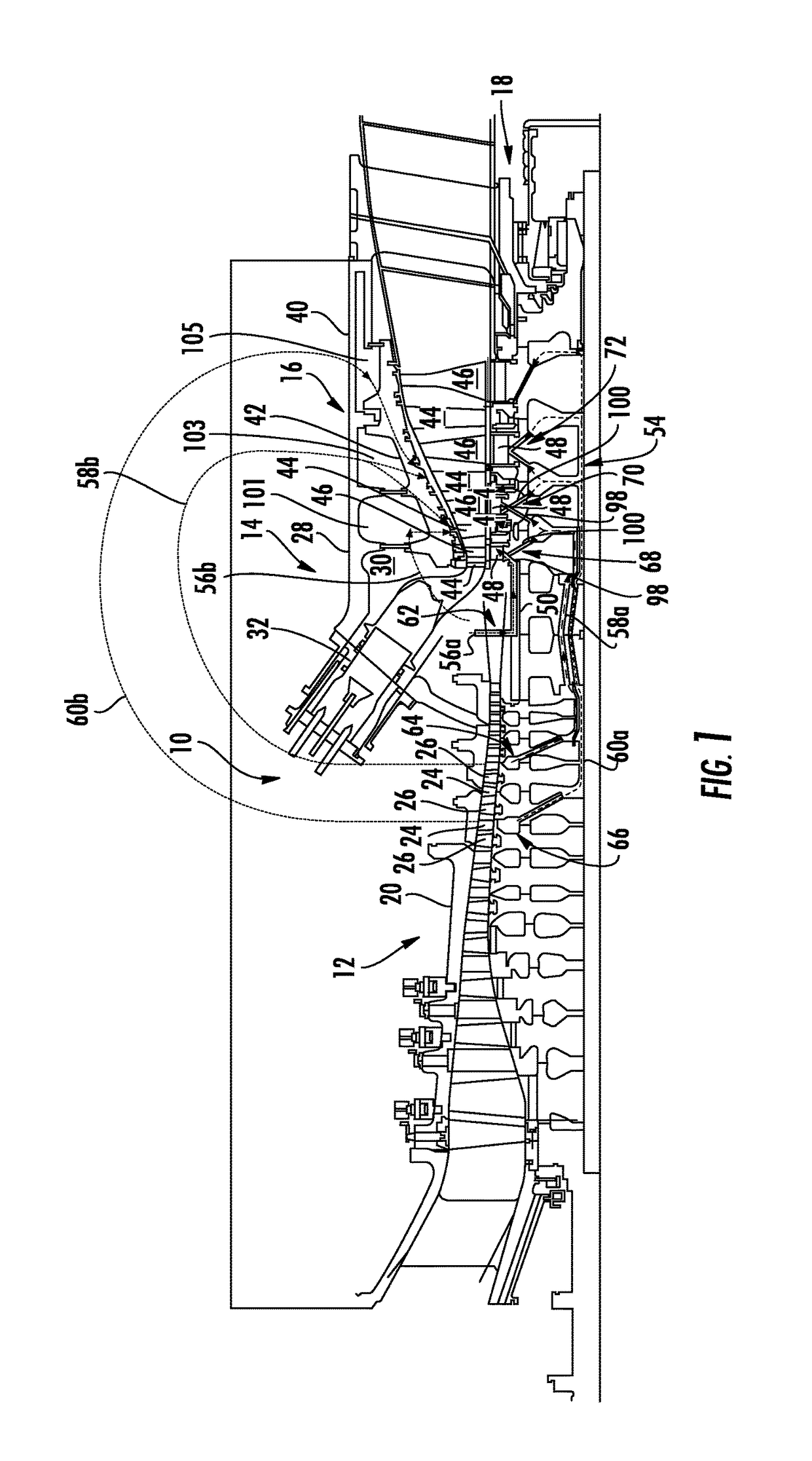
[0018]As shown in FIGS. 1-8, an airfoil cooling system 54 for a gas turbine engine 10 is disclosed. The airfoil cooling system 54 may be formed from at least a first cooling fluid supply system 56 in fluid communication with a first portion 62 of a compressor 12, and a second cooling fluid supply system 58 in fluid communication with a second portion 64 of the compressor 12. The first cooling fluid supply system 56 may be configured to supply cooling fluids at a first pressure from the first portion 62 of the compressor 12 to one or more airfoils of a first row of airfoils arranged circumferentially around a rotor assembly 18 of the gas turbine engine 10, and the second cooling fluid supply system 58 may be configured to supply cooling fluids at a second pressure from the second portion 64 of the compressor 12 to the one or more airfoils of the first row of airfoils. Additionally, the second pressure may be lower than the first pressure. As such, each of the one or more airfoils (su...


PUM


Abstract

An airfoil cooling system (54) for a gas turbine engine (10) is disclosed. The airfoil cooling system (54) may be formed from at least a first cooling fluid supply system (56), and a second cooling fluid supply system (58). The first cooling fluid supply system (56) may be configured to supply cooling fluids at a first pressure to one or more airfoils of a first row (68) of airfoils, and the second cooling fluid supply system (58) may be configured to supply cooling fluids at a second pressure to the one or more airfoils of the first row (68) of airfoils. Additionally, the second pressure may be lower than the first pressure. As such, each of the one or more airfoils may be cooled by cooling fluids at two different pressures. In particular embodiments, this may allow the airfoils to be cooled, while lowering the cost to the turbine engine (10) for providing such cooling.

Description

STATEMENT REGARDING FEDERALLY SPONSORED RESEARCH OR DEVELOPMENT[0001]Development of this invention was supported in part by the United States Department of Energy, Advanced Hydrogen Turbine Development Program, Contract No. DE-FC26-05NT42644. Accordingly, the United States Government may have certain rights in this invention.FIELD OF THE INVENTION[0002]This invention relates generally to gas turbine engines, and more particularly to cooling systems for turbine airfoils.BACKGROUND[0003]Turbine engines commonly include airfoils (such as turbine blades and / or turbine vanes) positioned within the turbine section of the turbine engine. This positioning may subject the airfoils to temperatures that can cause heat-related damage or failure in the airfoils. As such, the airfoils are typically cooled by a cooling system that supplies cooling fluids into the interior of the airfoils. This typical airfoil cooling system, however, may be deficient and / or may be ready for improvement.SUMMARY OF ...

Claims


Application Information

Patent Timeline
Patent Type & Authority Applications(United States)
IPC IPC(8): F01D5/18F01D25/12
CPCF01D5/186F01D25/12F01D5/187F05D2220/32F05D2240/301F05D2260/202F01D5/18
Inventor MARSH, JAN H.MARRA, JOHN J.SCRIBNER, CARMEN ANDREW
Owner SIEMENS ENERGY INC
Why Eureka
Try Eureka