Non-volatile memory device

a memory device and non-volatile technology, applied in the direction of memory adressing/allocation/relocation, instruments, input/output to record carriers, etc., can solve the problems of data logical invalidation, data rewrite performance decline, and the capacity of a flash memory device not being satisfied, so as to achieve the effect of suppressing the consumption of volatile memory

Active Publication Date: 2018-03-08
HITACHI LTD
View PDF0 Cites 20 Cited by
  • Summary
  • Abstract
  • Description
  • Claims
  • Application Information

AI Technical Summary

Benefits of technology

[0015]A write frequency of a non-volatile memory can be determined at a fine granularity while suppressing consumption of a volatile memory.

Problems solved by technology

However, the time required to erase one block's worth of data in the flash memory is longer than the time required to write one page's worth of data and, therefore, with a system which erases one block's worth of data every time one page's worth of data is rewritten, data rewrite performance of the flash memory declines.
However, since an increase in an amount of rewritten data may result in depleting the update area in the flash memory device, data logically invalidated by the update of data must be erased to change the storage area into a reusable state (a free area).
When rewrites of data concentrate on a specified block and the block becomes unusable due to an increase in the number of erases, in a worst-case scenario, a problem occurs in that, a part of the blocks reaching a rewrite limit and becoming unusable prevents capacity of a flash memory device from being satisfied despite other blocks being in a sound condition.
In a flash memory, a read error rate increases over time even with a page once written to.
Such an error is referred to as a retention error.
When using a logical-physical translation with a low degree of freedom, although a size of a logical-physical translation table can be suppressed, performance declines due to frequent occurrences of reclamation.
On the other hand, when using a logical-physical translation with a high degree of freedom, the size of the logical-physical translation table becomes enormous and control cost increases significantly.

Method used


Image

  • Non-volatile memory device
  • Non-volatile memory device
  • Non-volatile memory device

Examples


embodiment 1

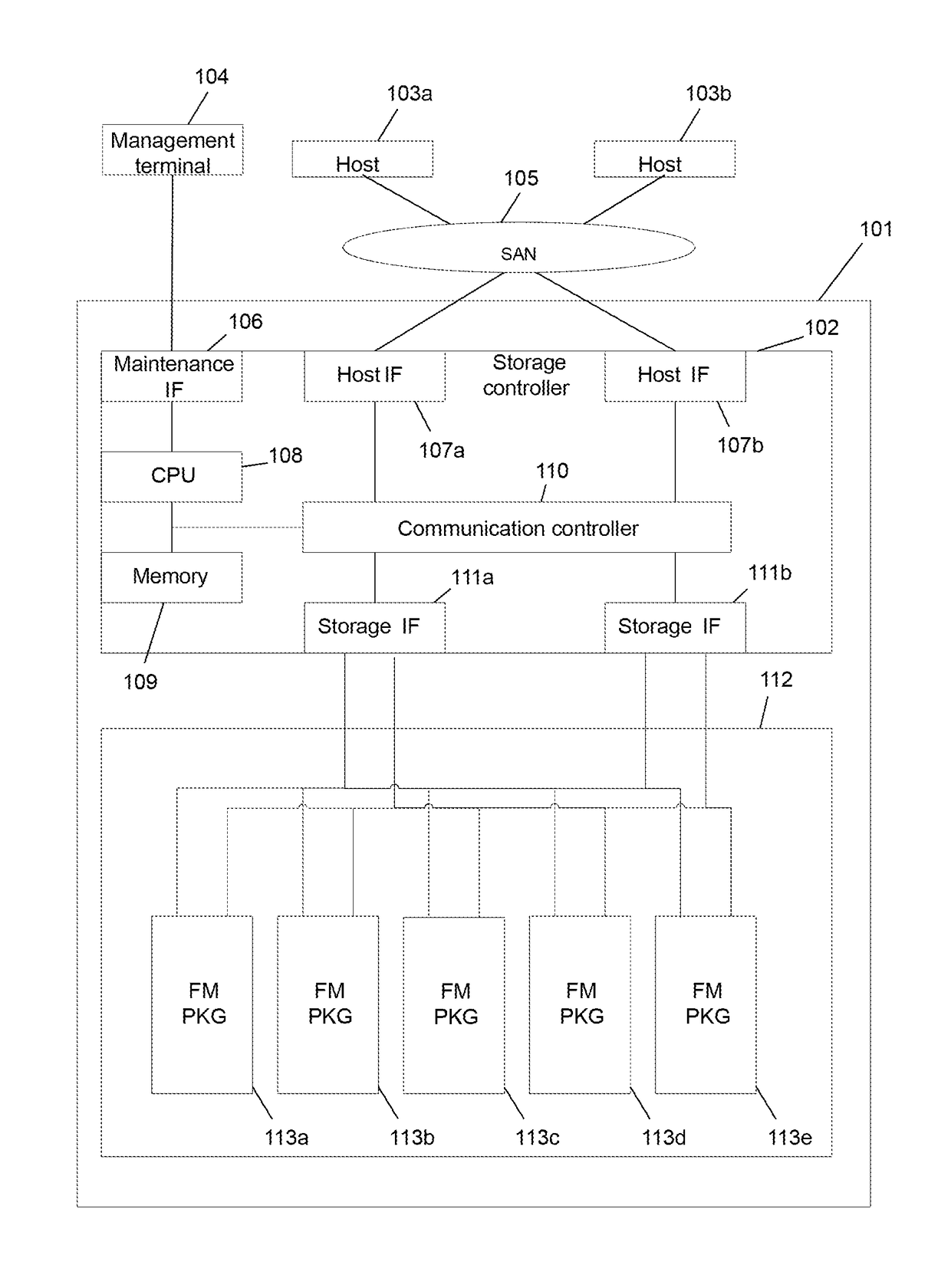
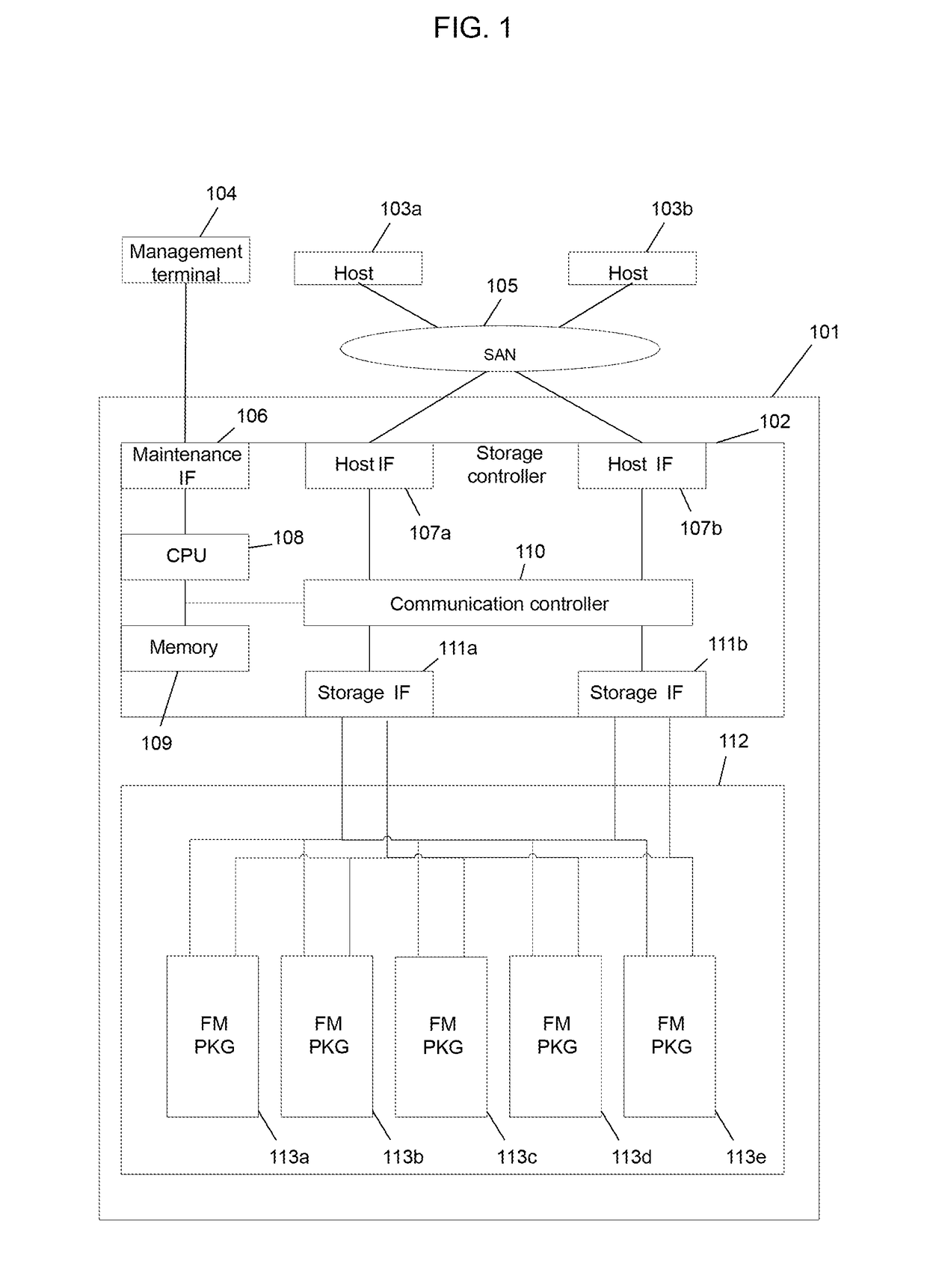
[0042]FIG. 1 shows a configuration of a computer system according to an embodiment.

[0043]The computer system includes a storage system 101, one or more host computers 103 (host computers 103a and 103b), and a management terminal 104. Each of the host computers 103a and 103b is coupled to the storage system 101 via a SAN (Storage Area Network) 105.

[0044]The storage system 101 includes a storage controller 102 and a plurality of flash memory storage apparatuses 113. In the drawings and in the following description, the flash memory storage apparatus 113 may be referred to as an FMPKG (Flash Memory Package). Moreover, while the present embodiment is provided with one storage controller 102, a redundant configuration which includes a plurality of storage controllers 102 may be adopted instead.

[0045]The storage controller 102 includes a CPU (Central Processing Unit) 108, a memory 109, a plurality of host IFs (Interfaces) 107 (host IFs 107a and 107b), a plurality of storage IFs 111 (stora...

embodiment 2

[0115]In Embodiment 1, an optimization method of a reclamation process involving classifying write frequencies and aggregating write destinations of classified data has been described. In the present embodiment, a method will be described in which physical areas that are write destinations are managed from a perspective of degradation degrees and wear leveling is realized by optimal matching of a write frequency and a degradation degree.

[0116]FIG. 13 shows a block degradation degree table.

[0117]The logical-physical translation information 306 includes a block degradation degree table 1301. The block degradation degree table 1301 includes a degradation degree 1302 for each block number 1302. The degradation degree is a quantification of a level of degradation of a block and may instead simply be, for example, the number of erases. Since it is known that degradation characteristics of a cell are not necessarily solely dependent on the number of erases, the degradation degree may inclu...


PUM


Abstract

A write frequency of a non-volatile memory is determined at a fine granularity while suppressing consumption of the volatile memory. When it is determined that a copy of specified data from a specified physical storage area to another physical storage area is to be executed, a controller reads the specified data and specified write frequency information, selects a write destination physical storage area group from a plurality of physical storage area groups based on the specified write frequency information and classification information, selects a write destination physical storage area from the write destination physical storage area group, changes the specified write frequency information, writes the specified data to the write destination physical storage area, writes the changed specified write frequency information to the non-volatile memory, and updates translation information based on the write destination physical storage area group and the write destination physical storage area.

Description

TECHNICAL FIELD[0001]The present invention relates to a non-volatile memory device.BACKGROUND ART[0002]A NAND flash memory (hereinafter, simply referred to as a flash memory or an FM) will be described. A flash memory cannot directly rewrite stored data and requires an erase process. A block is an erase unit of data and a page is a write / read unit of data. Hereinafter, unless otherwise specified, a simply-described block / page implies that the block / page belongs to a flash memory. A plurality of pages are provided in a single block.[0003]When a flash memory device that is a storage device using a flash memory rewrites data, the flash memory device first loads stored valid data to a storage device without an erase unit such as a DRAM (Dynamic Random Access Memory) and updates a necessary location. Next, the flash memory device performs an erase process on a block in which the data had originally been stored. Finally, the flash memory device writes data to the erased block. In this man...

Claims


Application Information

Patent Timeline
Patent Type & Authority Applications(United States)
IPC IPC(8): G06F12/02G06F3/06G11C16/34G11C16/16
CPCG06F12/0246G06F3/0647G11C16/16G06F3/0679G11C16/3495G06F3/064G06F3/0616G06F3/0652G06F2212/7201G06F2212/7202G06F2212/7205G06F2212/7207G06F3/0646G06F12/00G06F12/02G06F12/16
Inventor KAWAMURA, ATSUSHIARAI, MASAHIROFUJIMOTO, KAZUHISA
Owner HITACHI LTD
Why Eureka
Try Eureka