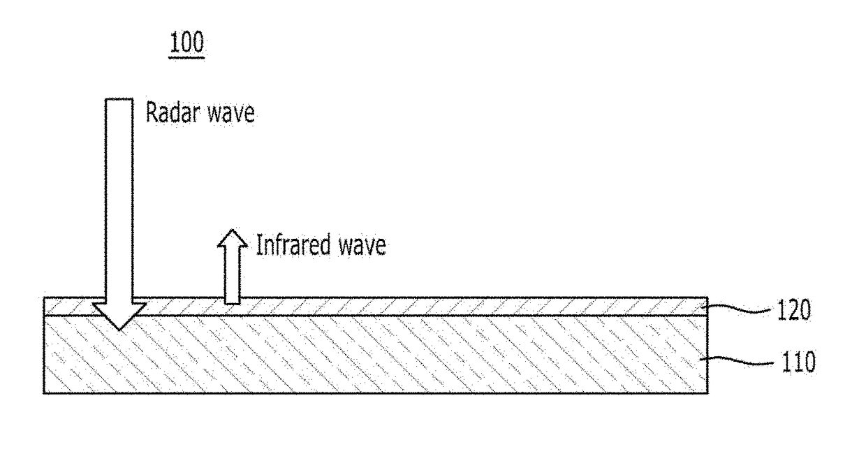
Composite structure for controlling absorptivity of radar and emissivity of infrared regions
a technology of infrared region and absorption structure, which is applied in the direction of optical radiation measurement, instruments, applications, etc., can solve the problems of difficult to verify the durability of the painting material, the method is not free from the phenomenon of easily eroding the painting material, and the painting material is difficult to detect. , to achieve the effect of improving the anti-detection function and lowering the probability of detection
- Summary
- Abstract
- Description
- Claims
- Application Information
AI Technical Summary
Benefits of technology
Problems solved by technology
Method used
Image

Examples
Embodiment Construction
[0037]The preferred embodiments of the invention will be hereafter described in detail with reference to the accompanying drawings.
[0038]It will be understood that the expressions and the predicates used in this application in relation to terms for directions of a device or an element, for example, the terms such as “up”, “down”, “top”, “bottom” and the like, are used only to simplify the description of the present invention and do not express or mean that a related device or element should necessarily have a specific direction.
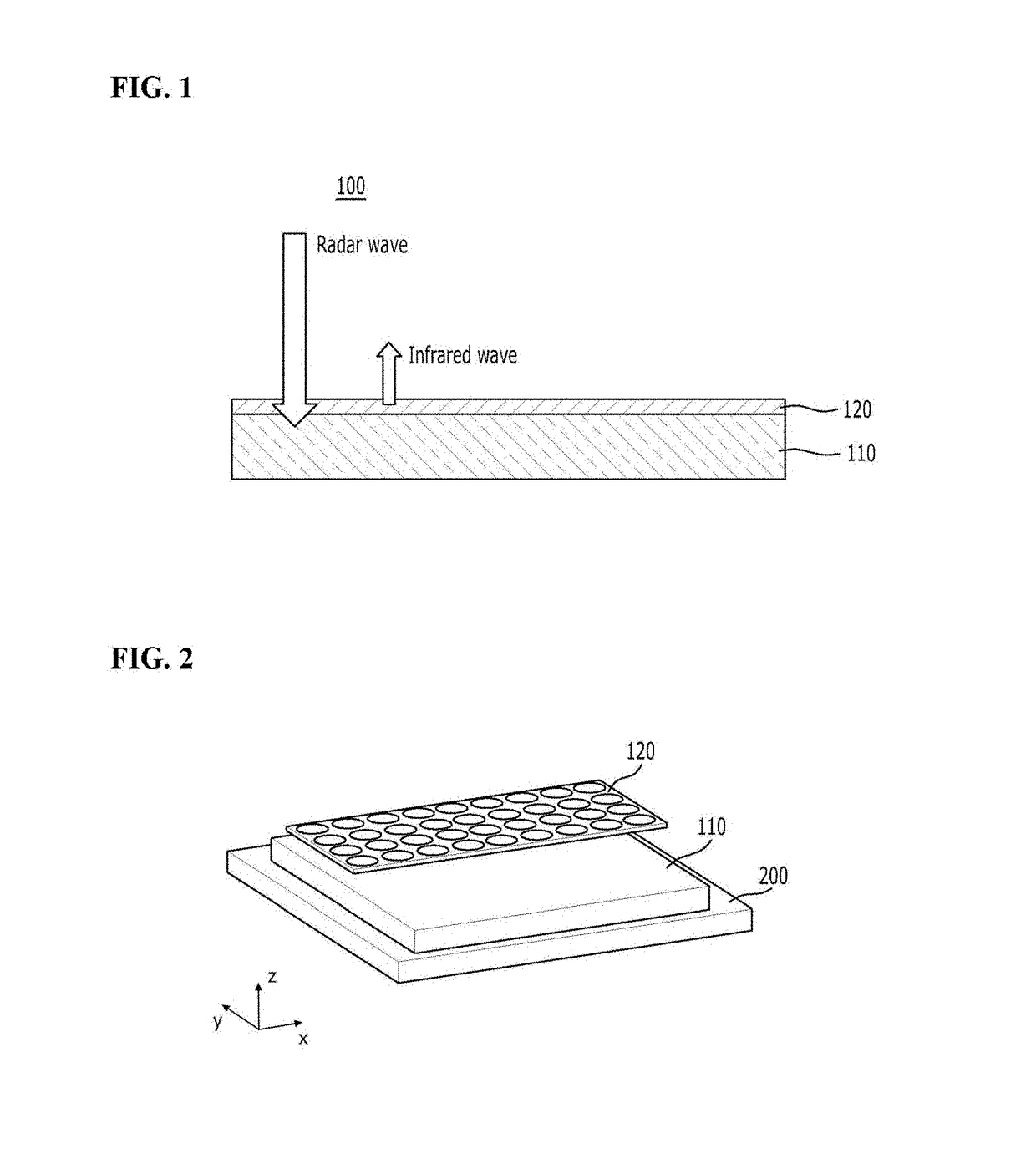
[0039]In the description below, the x-axis may mean the length direction of a composite structure for controlling absorptivity and emissivity, the y-axis may mean the width direction of the composite structure for controlling absorptivity and emissivity, and the z-axis may mean the height direction of the composite structure for controlling absorptivity and emissivity.
[0040]In addition, the expressions such as “first”, “second”, “third” and the like are expre...
PUM
| Property | Measurement | Unit |
|---|---|---|
| wavelength | aaaaa | aaaaa |
| wavelength | aaaaa | aaaaa |
| wavelength | aaaaa | aaaaa |
Abstract
Description
Claims
Application Information
 - R&D
- Intellectual Property
- Life Sciences
- Materials
- Tech Scout
- Unparalleled Data Quality
- Higher Quality Content
- 60% Fewer Hallucinations
Browse by: Latest US Patents, China's latest patents, Technical Efficacy Thesaurus, Application Domain, Technology Topic, Popular Technical Reports.
© 2025 PatSnap. All rights reserved.Legal|Privacy policy|Modern Slavery Act Transparency Statement|Sitemap|About US| Contact US: help@patsnap.com