
Thermoacoustic electric generator system

Active Publication Date: 2018-03-15
CENTRAL MOTOR WHEEL CO LTD
View PDF17 Cites 2 Cited by
  • Summary
  • Abstract
  • Description
  • Claims
  • Application Information

AI Technical Summary

Benefits of technology

The invention aims to reduce the cost and improve the maintenance of a linear generator in a thermoacoustic electric generator system. The system uses a thermoacoustic engine that does not have movable members to generate electric energy using the thermoacoustic oscillation of the working gas. However, the use of the linear generator is expensive. The invention proposes to adopt a cost-efficient and maintainable generator to create a practical system.

Problems solved by technology

However, use of the linear generator is disadvantageous in terms of cost because this linear generator itself is expensive.

Method used


Image

  • Thermoacoustic electric generator system
  • Thermoacoustic electric generator system
  • Thermoacoustic electric generator system

Examples


Embodiment Construction

[0019]A detailed description will hereinafter be made on one embodiment of the invention with reference to the drawings. Note that, in said drawings, in regard to each component of the same element that is denoted by the same reference sign for the description, a reference sign thereof for the description is omitted when necessary.

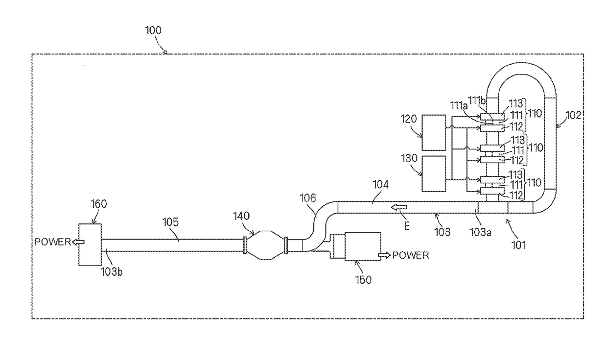
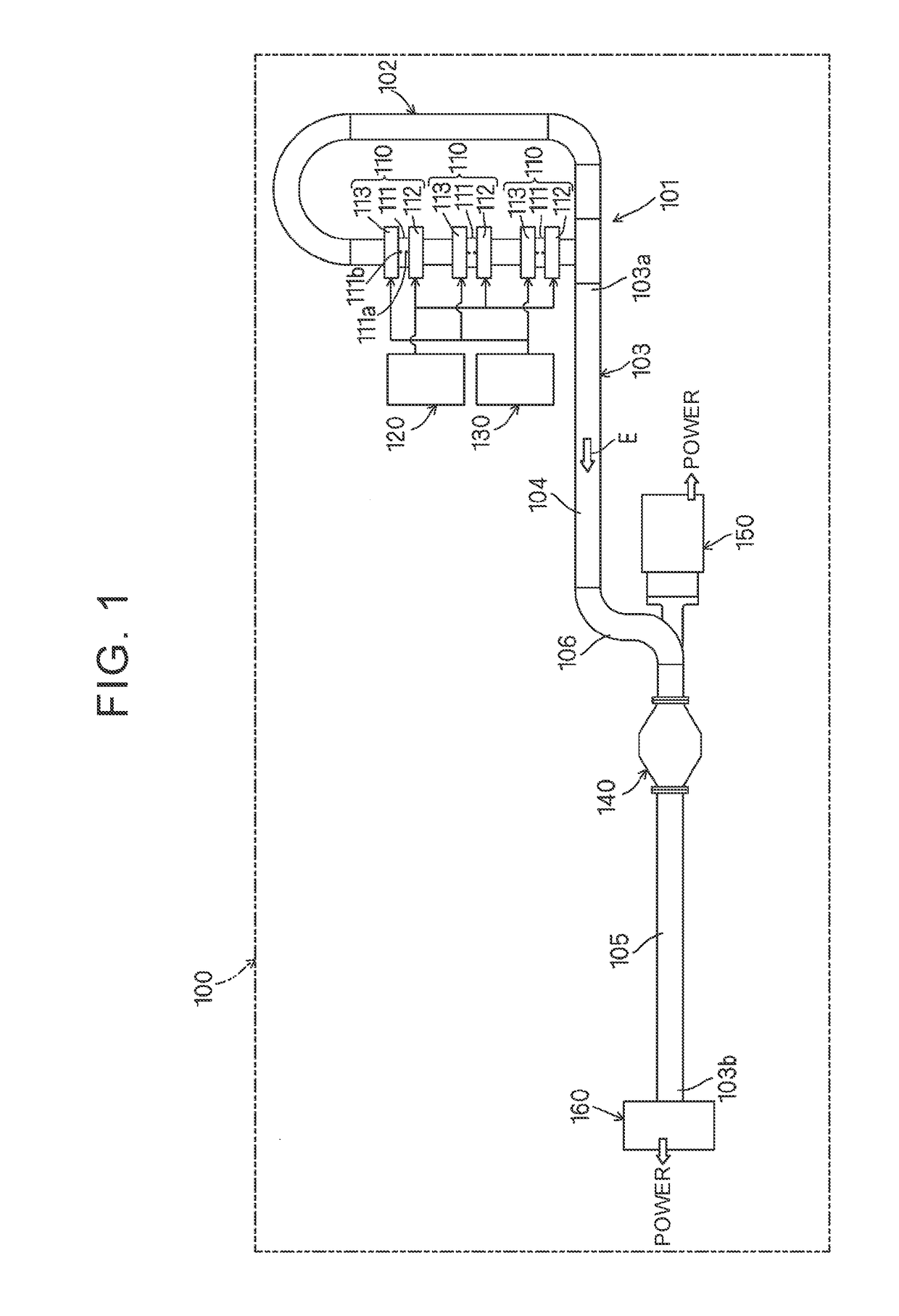
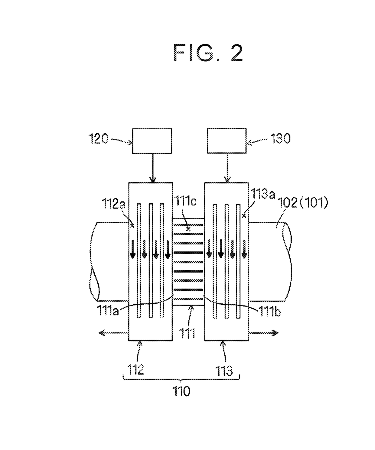
[0020]As shown in FIG. 1, a thermoacoustic electric generator system 100 includes a tube component 101 that is configured by including metallic tubes. This tube component 101 is configured by including: an annular tube 102 as an annular (loop) tube portion; and a branched tube 103 that is branched from the annular tube 102 and, an internal space of which communicates with an internal space of the annular tube 102. This tube component 101 corresponds to the “tube component” of the invention. In addition, the annular tube 102 and the branched tube 103 respectively correspond to the “annular tube” and the “branched tube” of the invention. Note that the annula...


PUM


Abstract

A thermoacoustic electric generator system includes: a turbine including a turbine blade provided in an inside of a branched tube in a tube component and rotating by thermoacoustic oscillation of working gas in a thermoacoustic engine, and a turbine rotational shaft configured to be coupled to the turbine blade, penetrate a tube wall of the branched tube, and extend from the inside to an outside thereof; and a generator provided on the outside of the branched tube in the tube component, coupled to the turbine rotational shaft of the turbine, and converting rotational energy of the turbine blade to electric energy.

Description

TECHNICAL FIELD[0001]The invention relates to a thermoacoustic electric generator system for generating electric energy using a thermoacoustic engine that induces thermoacoustic oscillation of working gas.BACKGROUND ART[0002]Conventionally, efficient energy use has been promoted in various industrial fields. However, a rate of exhaust heat, which is exhausted and wasted from facilities such as factories and vehicles, for example, still remains high. Thus, a technique of efficiently collecting thermal energy has been desired. In the earnest investigation into this technique, the present inventor has focused his attention on use of a thermoacoustic engine capable of inducing thermoacoustic oscillation of working gas. One example of a system (hereinafter also referred to as a “thermoacoustic electric generator system”) that generates electric energy using this thermoacoustic engine has been disclosed in PCT / JP / 2012-081193.[0003]The thermoacoustic engine used in this thermoacoustic elec...

Claims


Application Information

Patent Timeline
IPC IPC(8): F25B9/14F02G1/043
CPCF25B9/145F02G1/043F01D1/04F03G7/00F02G1/04F02C1/10F02C6/00F03G7/002F03G7/0252
Inventor FUKAYA, NORIYUKI
Owner CENTRAL MOTOR WHEEL CO LTD
Learn More