Supercharge Your Innovation With Domain-Expert AI Agents!

Input device

a technology of input device and electric resistance value, which is applied in the direction of electric digital data processing, instruments, computing, etc., can solve the problems of reducing waterproof and dustproof performance, difficult to reduce the thickness of input device, etc., and achieves the effect of simplifying the manufacturing process and increasing the electric resistance value of the load detection wir

Active Publication Date: 2018-03-15
ALPS ALPINE CO LTD
View PDF8 Cites 0 Cited by
  • Summary
  • Abstract
  • Description
  • Claims
  • Application Information

AI Technical Summary

Benefits of technology

The present invention provides an input device that can detect both position and weight applied through a thin and improved waterproof and dustproof performance. The device includes a position detection part with multiple electrodes and a load detection wire among the electrodes. The load detection wire has its electric resistance value that changes with pressure applied to it. This allows for detection of load through changes in electric resistance value without the need for a separate space for pressure detection.

Problems solved by technology

Due to the thickness of this type of variable space, it becomes difficult to reduce the thickness of the input device.
Another problem is that waterproof and dustproof performance are lowered.

Method used


Image

  • Input device
  • Input device
  • Input device

Examples


first embodiment

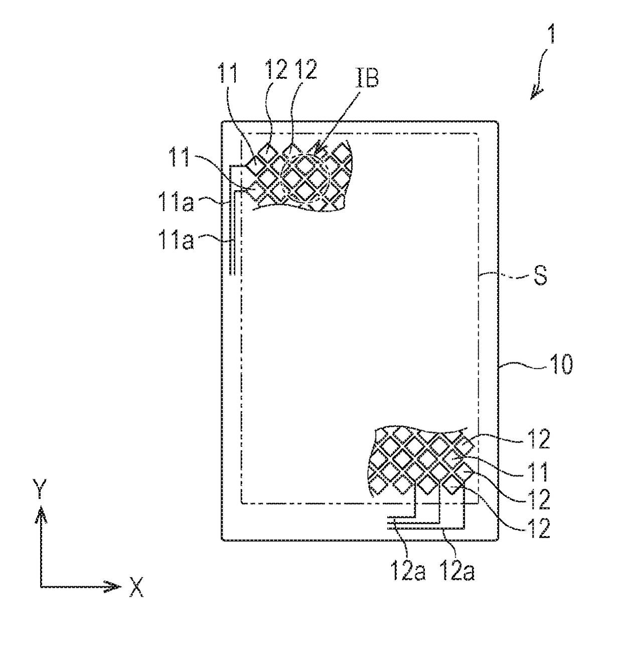
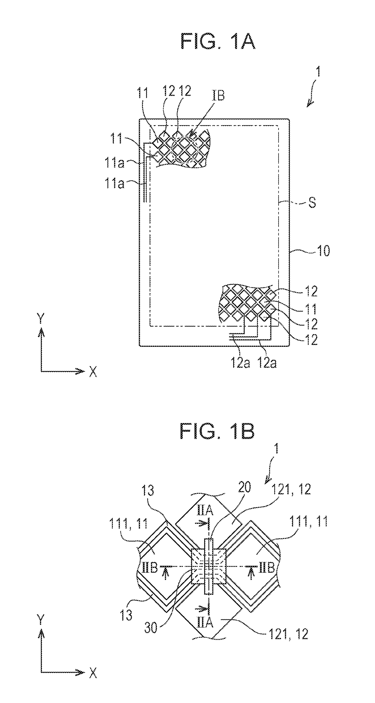
[0024]FIGS. 1A and 1B are each a plan view illustrating a capacitive sensor according to a first embodiment. FIG. 1A is an overall view of the capacitive sensor 1. FIG. 1B is an enlarged view of the portion IB in FIG. 1A. In this embodiment, the capacitive sensor 1 is an example of an input device.

[0025]As indicated in FIG. 1A, the capacitive sensor 1 according to this embodiment has first electrodes 11 and second electrodes 12 provided in a position detection part S of a base material 10. Each first electrode 11 and each second electrode 12 are a detection electrode that detects a position at which a finger has come into contact with or close to the position detection part S.

[0026]The first electrode 11 extends along the front surface of the base material 10 in the X direction, and the second electrode 12 extends along the front surface of the base material 10 in the Y direction, which is orthogonal to the X direction. The first electrode 11 and second electrode 12 are mutually iso...

second embodiment

[0048]FIG. 3 is a plan view illustrating a capacitive sensor according to a second embodiment. Specifically, FIG. 3 is an enlarged view of a portion equivalent to the portion IB in FIG. 1A.

[0049]In the capacitive sensor 1B according to this embodiment, a linkage part 112 of the first electrode 11 and the load detection wire 13 are provided on the island-shaped insulating part 30 at an intersection portion between the first electrode 11 and the second electrode 12.

[0050]The linkage part 112 is provided between two adjacent first island-shaped electrode parts 111 of the first electrode 11. The linkage part 112 is provided so as to link the opposing corners of the two adjacent first island-shaped electrode parts 111. A bridge part 122 is provided between two adjacent second island-shaped electrode parts 121 of the second electrode 12. The bridge part 122 is formed on the base material 10 so as to link the lower surfaces of the opposing corners of the two adjacent second island-shaped e...

third embodiment

[0055]FIGS. 5A and 5B each illustrate a capacitive sensor according to a third embodiment. FIG. 5A is an enlarged view of a portion equivalent to the portion IB in FIG. 1A. FIG. 5B is a cross sectional view taken along line VB in FIG. 5A.

[0056]In the capacitive sensor 1C according to this embodiment, the load detection wire 13 is divided at the position of the island-shaped insulating part 30. The load detection wire 13 preferably has first wiring parts 131 and a second wiring part 132.

[0057]The second wiring part 132 is disposed below the island-shaped insulating part 30 and between the divided first wiring parts 131. One of both ends of the second wiring part 132 overlaps with an end of one divided first wiring parts 131, and the other end of the second wiring part 132 overlaps with an end of another divided first wiring parts 131. The bridge wiring part 20 is provided so as to pass over the second wiring part 132 with the island-shaped insulating part 30 interposed between them.

[...


PUM


Abstract

As an input device that can detect both a position and an applied weight and has a thin thickness and improved waterproof and dustproof performance, an input device is provided that has a position detection part provided on a base material, the position detection part having a plurality detection electrodes, and also has a load detection wire provided among the plurality of detection electrodes in the position detection part, the electric resistance value of the load detection wire changing depending on pressure. In the input device, the plurality of detection electrodes may have first electrodes and second electrodes that both extend in mutually intersecting directions, each first electrode may have a bridge wiring part provided at an intersection position between the first electrode and the second electrode, and the load detection wire may be provided so as to intersect the bridge wire.

Description

CLAIM OF PRIORITY[0001]This application is a Continuation of International Application No. PCT / JP2016 / 065667 filed on May 27, 2016, which claims benefit of Japanese Patent Application No. 2015-170635 filed on Aug. 31, 2015. The entire contents of each application noted above are hereby incorporated by reference.BACKGROUND OF THE INVENTION1. Field of the Invention[0002]The present invention relates to an input device, and more particularly to an input device that includes a plurality of detection electrodes used to detect a position on a base material.2. Description of the Related Art[0003]In various types of information processing apparatuses, a translucent input device is placed in front of a color liquid crystal display panel. This type of input device is called a touch panel. In a touch panel, capacitance is formed between electrodes. When a finger of a person comes close to the touch panel, a change occurs in the movement of charges. The coordinates of the close position of the ...

Claims


Application Information

Patent Timeline
Patent Type & Authority Applications(United States)
IPC IPC(8): G06F3/044
CPCG06F3/044G06F2203/04111G06F2203/04103G06F2203/04105G06F3/0443G06F3/0446
Inventor MOGI, TOSHIYUKIASANO, ISAO
Owner ALPS ALPINE CO LTD
Features
  • R&D
  • Intellectual Property
  • Life Sciences
  • Materials
  • Tech Scout
  • Unparalleled Data Quality
  • Higher Quality Content
  • 60% Fewer Hallucinations
Learn More