Panel with a slider

Active Publication Date: 2018-03-22
VÄLINGE INNOVATION AB
View PDF53 Cites 37 Cited by
  • Summary
  • Abstract
  • Description
  • Claims
  • Application Information

AI Technical Summary

Benefits of technology

[0004]It is an object of certain embodiments of the present invention to provide an improvement over the above described techniques and kn

Problems solved by technology

A drawback with the known systems is that it time

Method used


Image

  • Panel with a slider
  • Panel with a slider
  • Panel with a slider

Examples


Example

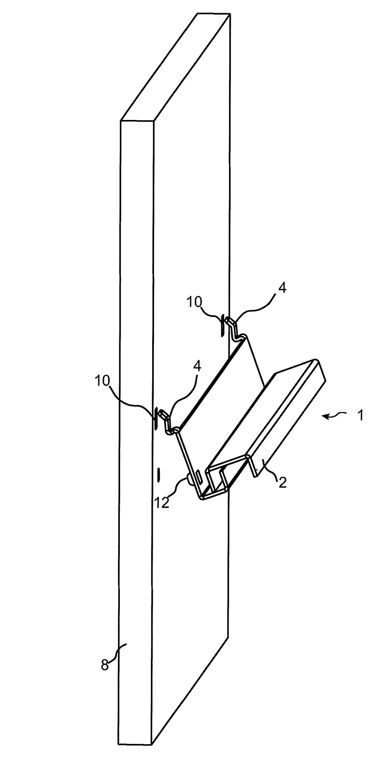
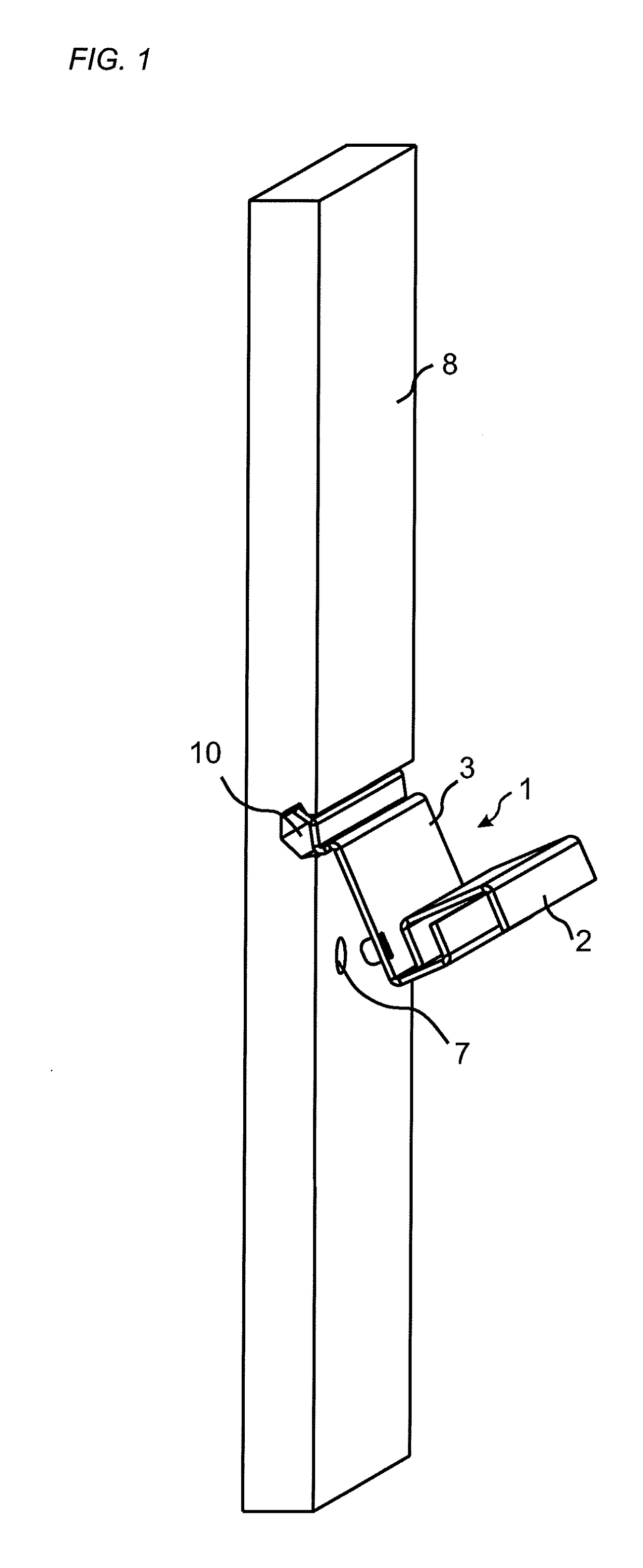
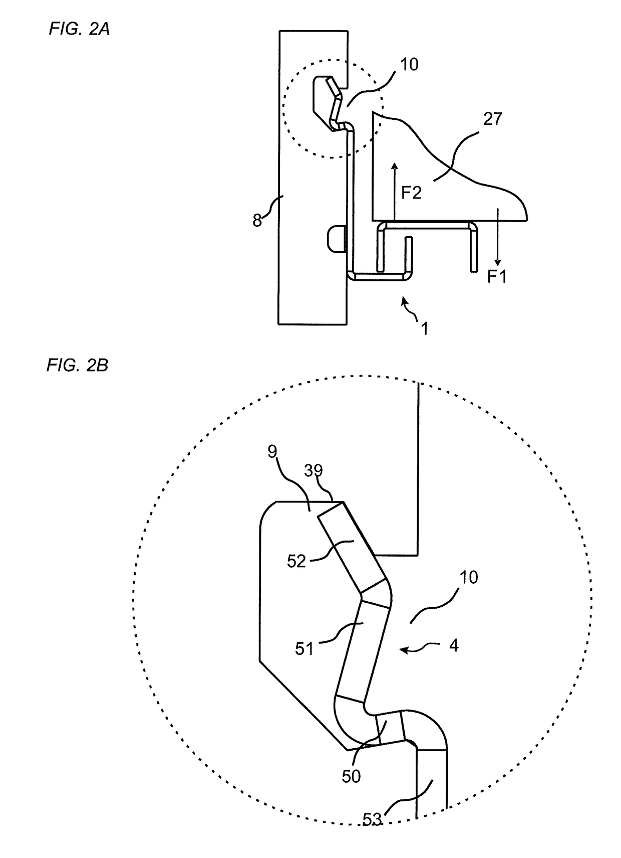
[0035]An embodiment of the invention is shown in FIG. 1 during assembling and in an assembled position in FIG. 2A. FIG. 2B shows an enlargement of the encircled area of FIG. 2A, which shows a schematic drawing of a panel 8 and a slider 1. The embodiment includes a set, which may be a part of a furniture or kitchen furnishing, comprising a panel 8 and a slider 1, such as a drawer slider. FIG. 3A shows the slider parts of FIG. 2B and FIG. 3B shows the panel parts of FIG. 2B. The panel may be of a rectangular shape and arranged such that it extends in a vertical direction. The slider may comprise an inner part 3, which is assembled to the panel, and an outer part, which is configure to be connected to a drawer (schematically shown in FIG. 2B). The outer part is displaceable relative the inner part. The slider comprises a slider surface 15 and the panel comprising a panel surface 16, as is shown in FIGS. 3A and 3B, respectively. The slider is configured to be assembled to the panel with...


PUM

PropertyMeasurementUnit
Angleaaaaaaaaaa
Distanceaaaaaaaaaa

Abstract

A set including a panel and a slider, such as a drawer slider. The slider including a slider surface and the panel comprising a panel surface. The slider is configured to be assembled to the panel with the slider surface facing the panel surface. The panel surface is provided with an insertion groove and an undercut groove, which are of a longitudinal shape. A strip protrudes from the slider surface, and the strip is configured to be inserted into the insertion groove and the undercut groove by an angling motion.

Description

TECHNICAL FIELD OF THE INVENTION[0001]The present invention relates to a fastening device for connecting a runner, such as a drawer runner to a panel, such as a building panel, a wall panel, furniture component or the like.TECHNICAL BACKGROUND[0002]Drawer sliders are known that are fixed to e.g. furniture by screws. A drawback with the known systems is that it time consuming to assemble the sliders to the furniture.[0003]The above description of various known aspects is the applicant's characterization of such, and is not an admission that any of the above description is considered as prior art.SUMMARY OF THE INVENTION[0004]It is an object of certain embodiments of the present invention to provide an improvement over the above described techniques and known art. Particularly to reduce the time for assembling and the strength of the locking system is improved by embodiments of the invention.[0005]At least some of these and other objects and advantages that will be apparent from the d...

Claims


Application Information

Patent Timeline
IPC IPC(8): F16B12/12A47B88/43
CPCF16B12/12A47B88/43A47B2210/0056F16B12/26A47F5/0846
Inventor DERELOV, PETER
Owner VÄLINGE INNOVATION AB
Why Eureka
Try Eureka