
Method, apparatus and system for encoding and decoding video data

a video data and video technology, applied in the field of digital video signal processing, can solve the problems of tight coupling of the encoding and decoding process, increased cable routing complexity, and reduced achievable cabling length

Active Publication Date: 2018-03-22
CANON KK
View PDF16 Cites 48 Cited by
  • Summary
  • Abstract
  • Description
  • Claims
  • Application Information

AI Technical Summary

Benefits of technology

The present invention provides a method, apparatus, and computer programmer for encoding a coding tree unit in a video bitstream. The method involves forming a plurality of candidate configurations for the coding tree unit, each with variations in partitioning modes and encoding parameters, selecting a candidate configuration based on a predetermined maximum bit rate for the coding tree unit, and encoding the coding tree unit using the selected candidate configuration. These arrangements improve the performance and efficiency of video bitstreams. Previous methods and arrangements had limitations in terms of performance and efficiency, and the present invention provides a solution to overcome these limitations.

Problems solved by technology

However, the signalling is insufficient to achieve very low latencies with minimal buffering, and consequently results in tight coupling of the encoding and decoding processes.
As bit rates increase, achievable cabling lengths reduce, which becomes problematic for cable routing through a studio.
However, the cabling replicating method increases cable routing complexity, requires more physical space, and may reduce reliability compared to use of a single cable.
However, reducing sampling of the colour channels without causing undue visual impactis less applicable to studio environments, where multiple generations of encoding and decoding are common.
Also, for screen content the use of chroma formats other than 4:4:4 can be problematic as distortion is introduced to sub-pixel rendered (or ‘anti-aliased’) text and sharp object edges.
Generally, regions of detailed textures (e.g. foliage, text), or regions containing noise (e.g. from a camera sensor) are difficult to compress.
In the context of real-time operation, it is not possible to stall input or delay output (e.g. due to buffer overrun or underrun).
If input was stalled or output delayed, the result would be some highly noticeable distortion of the video data being passed through the video encoder and decoder.

Method used


Image

  • Method, apparatus and system for encoding and decoding video data
  • Method, apparatus and system for encoding and decoding video data
  • Method, apparatus and system for encoding and decoding video data

Examples


Embodiment Construction

[0055]Where reference is made in any one or more of the accompanying drawings to steps and / or features, which have the same reference numerals, those steps and / or features have for the purposes of this description the same function(s) or operation(s), unless the contrary intention appears.

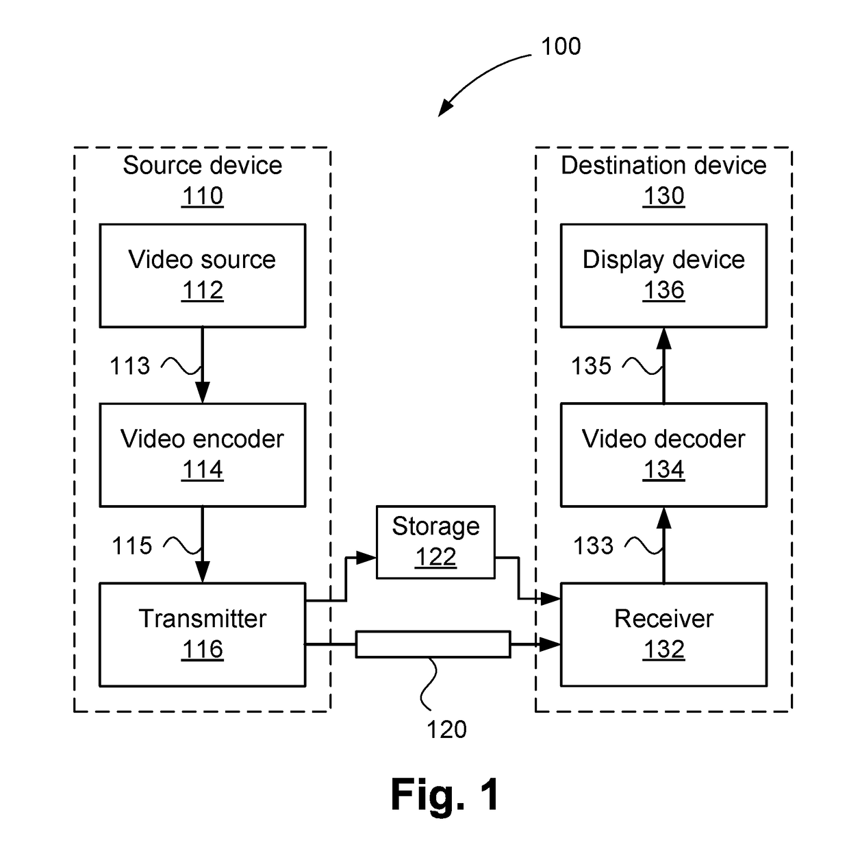
[0056]FIG. 1 is a schematic block diagram showing function modules of a sub-frame latency video encoding and decoding system 100. The system 100 may use a rate control and buffer management mechanism to ensure delivery of portions of a frame by video encoder 114 within a timeframe that allows video decoder 134 to deliver decoded frame data in real time.

[0057]The rate control and buffer management mechanism ensures that no buffer underruns and resulting failure to deliver decoded video occur (e.g. due to variations in the complexity and time taken for encoder searching of possible modes) of the incoming video data to the video encoder 114), so that decoded video frames from the video decoder 134 are...


PUM


Abstract

A method of encoding a coding tree unit in a video bitstream. A plurality of candidate configurations are formed for the coding tree unit, each of the candidate configurations having a variation of at least one of a set of partitioning modes and encoding parameters. A candidate configuration is selected from the plurality of candidate configurations based on a predetermined maximum bit rate for the coding tree unit, the selected candidate configuration having a size within the predetermined maximum bit rate. The coding tree unit is encoded using the selected candidate configuration.

Description

REFERENCE TO RELATED PATENT APPLICATION(S)[0001]This application claims the benefit under 35 U.S.C. § 119 of the filing date of Australian Patent Application No. 2016231584, filed Sep. 22, 2016, hereby incorporated by reference in its entirety as if fully set forth herein.TECHNICAL FIELD[0002]The present invention relates generally to digital video signal processing and, in particular, to a method, apparatus and system for encoding and decoding video data. The present invention also relates to a computer program product including a computer readable medium having recorded thereon a computer program for encoding and decoding video data.BACKGROUND[0003]Many applications for video coding currently exist, including applications for transmission and storage of video data. Many video coding standards have also been developed and others are currently in development. Recent developments in video coding standardisation have led to the formation of a group called the “Joint Collaborative Team...

Claims


Application Information

Patent Timeline
IPC IPC(8): H04N19/96H04N19/91H04N19/19H04N19/124H04N19/159
CPCH04N19/96H04N19/91H04N19/19H04N19/124H04N19/159H04N19/176H04N19/119H04N19/147H04N19/103H04N19/186H04N19/146
Inventor ROSEWARNE, CHRISTOPHER JAMESKOLESNIKOV, VOLODYMYR
Owner CANON KK
Learn More