Cover for an ultra-flat panel display

a technology for video display units and display covers, which is applied in the direction of identification means, electrical apparatus casings/cabinets/drawers, instruments, etc., can solve the problems of inapplicability to consumers, cost hundreds of dollars, and the like, and achieves the effects of low cost, easy installation, and light weigh

Active Publication Date: 2018-03-22
PECORINO PHILIP +1
View PDF3 Cites 9 Cited by
  • Summary
  • Abstract
  • Description
  • Claims
  • Application Information

AI Technical Summary

Benefits of technology

[0015]The present invention is an improvement in the art for cover units for video display panels. Because the ultra-thin video display units offered today are lighter in weight, the present invention discloses a system that is lightweight and easy to install. Further, the cover unit of the present invention is low in cost, adapts easily to a variety of different size display units, has an art roller assembly that can be changed by the consumer and which can easily be mounted or moved by the consumer.
[0016]One illustrative embodiment of the cover unit of the present invention includes mounting brackets or a mounting bar that supports the weight of the entire cover unit. The mounting bracket(s) or mounting bar is easy to install on a wall by a consumer with anchor bolts or other securing means. The housing for the cover unit is mounted on the brackets or bar, and includes a roller mount to receive a roller, a grooved channel to receive a matte and display panel, and a cover channel to allow for a cover with artwork to be rolled up and down in front of the display panel. Decorative front and side pieces, such as a frame, may be added to the housing. The roller within the housing can be easily snapped or slid into place through the top or side of the housing. This allows the consumer to change out the cover or artwork at will. The matte allows for off-the-shelf purchase of the cover unit, and ensures that only the screen of the display unit or the artwork on the cover is viewable. This allows the consumer to use the same cover unit with multiple sizes of display units or artwork, only having to change or cut the matte. The design of the housing further permits consumers to easily insert and remove the display unit and matte. Also, the roller is controlled by a motor that rotates the roller in one direction or the other in response to a control signal, perhaps from a television remote control unit or similar device.
[0017]This invention represents a major step in allowing consumers to purchase inexpensive off-the-shelf cover units that do not require custom manufacturing or installation.

Problems solved by technology

Several years ago flat panel video display televisions cost thousands of dollars.
Today they cost hundreds of dollars.
It is also not practical for the consumer to have the flat panel television remain turned on displaying a picture when the device is not being watched, because this will significantly reduce the lifespan of the display unit.
This was a reasonable expense to improve home aesthetics when the cost of the television was even greater.
However, with the drop in the cost of the television, purchase of such devices becomes a more difficult choice.
Further, it is burdensome for the consumer to obtain and install the cover described in the '765 patent.
This results in an order and installation process that is very expensive and time consuming for the consumer who wishes to use such a cover, over and above the cost of the cover unit itself.
The cover unit described in the '765 patent also was not amenable to a customer easily changing out the flat panel video display or the art work in the cover unit.
The artwork in this unit is not easily changed by the customer.
Also, the combination of the flat display panel and cover unit is not easily moved by the customer.
While the '400 publication allows a single cover unit to be used with a variety of flat panel screen and art print sizes, it does not solve any of the other problems described above for the '765 and '987 patents.

Method used


Image

  • Cover for an ultra-flat panel display
  • Cover for an ultra-flat panel display
  • Cover for an ultra-flat panel display

Examples


first embodiment

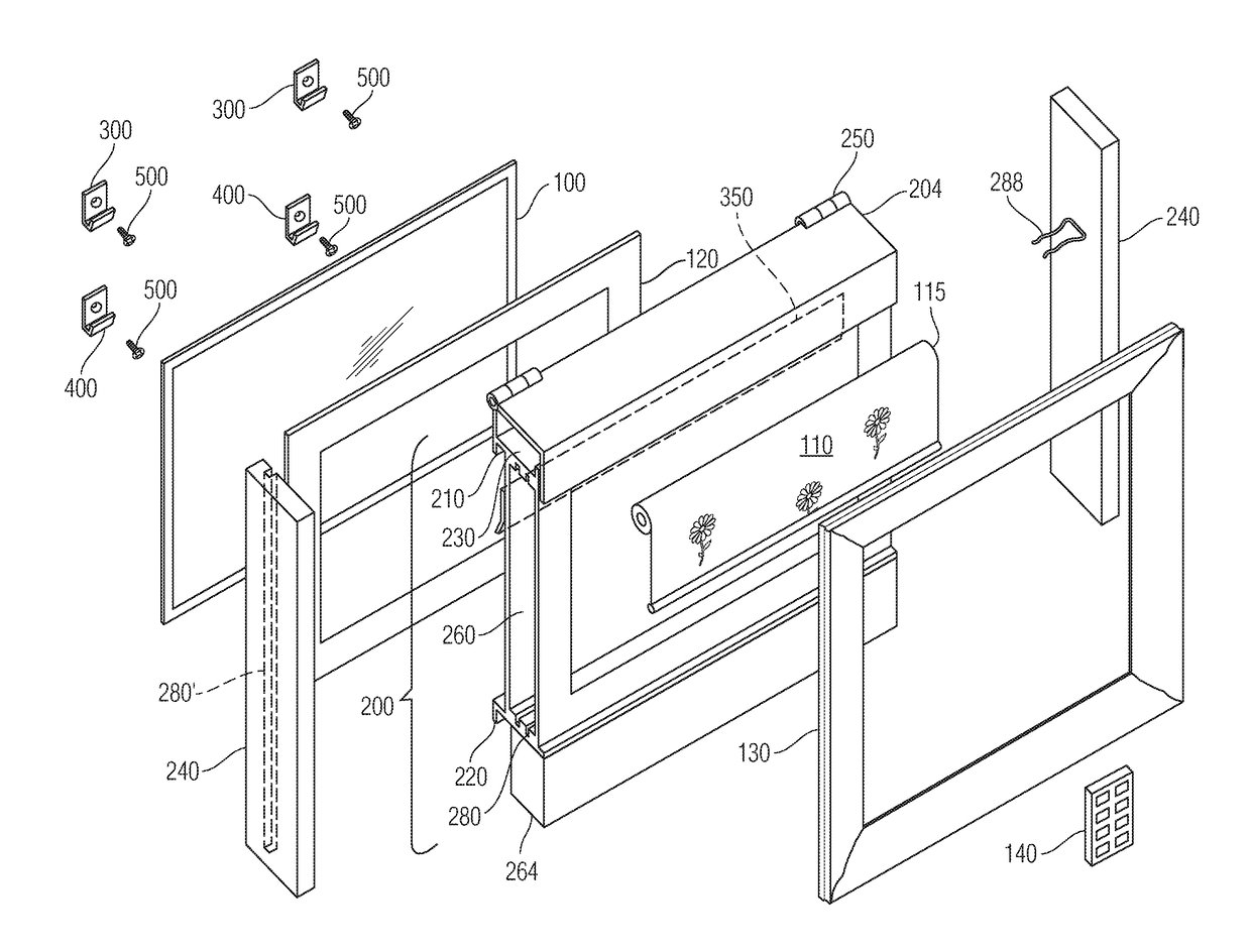
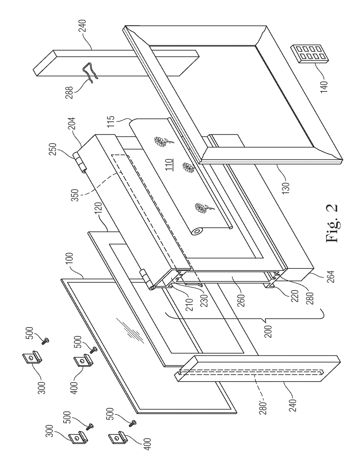
[0035]In a first embodiment, as shown in FIGS. 2 and 3, mounting brackets 300 and 400 are located on the four corners of the housing. These mounting brackets can be anchored into a wall with screws, bolts or other similar securing mechanisms 500. See also FIG. 8B. See FIG. 3. Other hanging mechanisms, such as using wire or clips on the housing, can be used. The mounting brackets 300 and 400 support the weight of the entire cover unit system, including the flat display panel, and are easy to install by a consumer or retailer. Alternatively, a mounting bar 350 or other device for mounting can be used. The mounting brackets 300 and 400 or bar 350 are of equal depth so as to hold the housing at equal distances on all sides from the wall on which it is mounted. In the present invention, at least the two upper mounting brackets 300 or the mounting bar bear the weight of the entire cover unit system, which includes at least the housing 200, frame 130, display unit 100, roller 115, and matt...

third embodiment

[0049]In a third embodiment, as shown in FIGS. 9 and 10, the cover unit rests on an easel 700 on a table or floor so that it looks like a picture, rather than being hung on a wall.


PUM


Abstract

An improved cover unit for thin flat display panels provides consumers with the ability to purchase and install a cover unit without the aid of a skilled technician. The cover unit is for use with flat panel displays, including ultra-thin displays, which are thin and lightweight. The cover unit is secured to a wall with mounting brackets, and has a housing that supports the frame, display unit, a matte and a roller on which a cover is mounted. The cover has artwork on it, which is displayed when it is rolled down to conceal the flat display panel, but which can be rolled up out of the way when the display unit is in operation. The matte allows for a single cover unit to accommodate a variety of display screen and artwork sizes. In this system, the roller, display unit and matte are easily inserted and removed from the housing.

Description

CROSS-REFERENCE TO RELATED APPLICATION[0001]The present application claims priority to U.S. Provisional Patent Application No. 62 / 396,576, entitled COVER FOR AN ULTRA-FLAT PANEL DISPLAY, filed on Sep. 19, 2016, the contents of which are hereby incorporated by reference as if set forth expressly in its entirety.FIELD OF THE INVENTION[0002]The present invention relates to a display cover for a flat screen video display unit that is mounted to a wall, and particularly to an art cover unit for an ultra-flat panel display which can be purchased off the shelf, easily installed by a consumer, and used with a variety of different sized ultra-flat panel displays.BACKGROUND OF THE INVENTION[0003]The use of flat panel video displays, such as flat panel televisions, has become increasingly widespread. Flat panel televisions are becoming more and more affordable for consumers as the technology improves. In addition, the variety of sizes of the displays of these flat panel televisions has increas...

Claims


Application Information

Patent Timeline
Patent Type & Authority Applications(United States)
IPC IPC(8): H05K5/02G09F11/08G09F11/10H05K5/03H04N5/645
CPCH05K5/0243G09F11/08G09F11/10H05K5/03H04N5/645E06B9/40
Inventor PECORINO, PHILIPMEDAGLIA, ALDO
Owner PECORINO PHILIP
Why Eureka
Try Eureka