Unlock instant, AI-driven research and patent intelligence for your innovation.

Rail cooling system and method for reducing thermal expansion

Active Publication Date: 2018-03-29
SIEMENS MOBILITY INC
View PDF4 Cites 2 Cited by
  • Summary
  • Abstract
  • Description
  • Claims
  • Application Information

AI Technical Summary

Benefits of technology

The present invention is about cooling a rail of a railway track to counter problems caused by the sun's heat. A cooling module is mounted on the rail's side to remove heat and also power electric loads associated with the railway infrastructure, such as lights or communication devices. The cooling system can detect potential rail thermal expansion and communicate it in a timely manner. This invention can be used in different environments where cooling is needed, such as railway installations.

Problems solved by technology

Such temperature variations cause rails of a railway track to move from its installed position.
For example, longitudinal expansion in rail due to radiant heating by the sun in summer causes track distortion and buckling, but successive contraction in winter also causes breakage in the rails.
This natural opposing behavior of the rails impacts operational safety and increases cost of track maintenance in places where drastic difference in temperature is encountered in a seasonal change under extreme weather conditions.
Rail thermal expansion in track is a problem because heating of rails changes the shape of rails so a track structure ends with a perpetual movement.
However, under the extreme heating and cooling cycles of certain days, thermal energy injected into railroad rail by the sun can cause severe thermal expansion.
With the elimination of rail joints, unrestrained thermal expansion can cause CWR sections to shift non-linearly, causing detrimental conditions for railroad operations and can lead to derailments and loss of time due to track maintenance.
Catastrophic failure results in the form of lateral distortion (bulge).
This installation technique results in the sections of rail being placed in tension (pulled) when they cool.
This presents a problem in that tensioned rail is prone to breakage during cold weather.
Trains passing over a tensioned section of rail can cause the steel to break and pull apart since it is tensioned.
The rails remain lashed to the ties but the ties and the ballast integrity fails under the lateral forces.
Even using stronger substrate, given enough expansion forces, the lashing has a chance to fail, resulting in rail buckling.

Method used


Image

  • Rail cooling system and method for reducing thermal expansion
  • Rail cooling system and method for reducing thermal expansion
  • Rail cooling system and method for reducing thermal expansion

Examples


Embodiment Construction

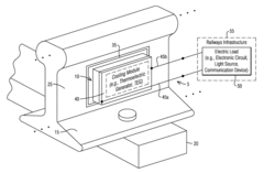
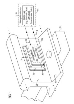
[0025]To facilitate an understanding of embodiments, principles, and features of the present invention, they are explained hereinafter with reference to implementation in illustrative embodiments. In particular, they are described in the context of removing thermal energy from the rail to cool it and use the extracted or harnessed heat to drive an electric load such as a circuit, a light or a device. Embodiments of the present invention, however, are not limited to use in the described devices or methods.

[0026]The components and materials described hereinafter as making up the various embodiments are intended to be illustrative and not restrictive. Many suitable components and materials that would perform the same or a similar function as the materials described herein are intended to be embraced within the scope of embodiments of the present invention.

[0027]A thermal energy removal system is provided for cooling a rail of a railway track. The system comprises a cooling module confi...


PUM


Abstract

A thermal energy removal system is provided to cool a rail of a railway track in a self-powered mode and / or an externally-powered mode. The system comprises a cooling module configured to mount on a side of the rail to remove heat stored inside the rail. The cooling module includes a solid state electrical insulation sandwiched between a plate and a heat sink. The cooling module further includes a first terminal and a second terminal. The first and second terminals to provide an electric energy source based on the heat extracted and harnessed for powering at least one of an electronic circuit, a light source, and a communication device associated with railways infrastructure.

Description

CROSS REFERENCE TO RELATED APPLICATIONS[0001]This application claims the benefit of U.S. Provisional Application Ser. No. 62 / 143,349 entitled “RAILROAD RAIL BUCKLE PREVENTION USING THERMOELECTRIC GENERATOR,” filed on Apr. 6, 2015, the contents of which are hereby incorporated by reference herein in their entirety.BACKGROUND1. Field[0002]Aspects of the present invention generally relate to altering condition of a railways installation such as a railway track and more specifically relates to a cooling device for removing thermal energy from rails of the railway track to avoid detrimental conditions for railroad operations and reduce track maintenance.2. Description of the Related Art[0003]Due to constant weather changes temperature varies throughout the year in most locations. Such temperature variations cause rails of a railway track to move from its installed position. For example, longitudinal expansion in rail due to radiant heating by the sun in summer causes track distortion and...

Claims


Application Information

Patent Timeline
IPC IPC(8): F25B21/04B61L1/02H01L35/30
CPCF25B21/04B61L1/02H01L35/30F25B2321/021F25B2321/0212F25B2321/023B61L1/20B61L11/00B61L13/00E01B19/00H10N10/00H10N10/13
Inventor DEJARNATT, BARTONPLESS, TRAVIS
Owner SIEMENS MOBILITY INC