Eureka AIR delivers breakthrough ideas for toughest innovation challenges, trusted by R&D personnel around the world.

Three-dimensional image formation and color correction system and method

Active Publication Date: 2018-03-29
CHANG JIANG +2
View PDF1 Cites 12 Cited by
  • Summary
  • Abstract
  • Description
  • Claims
  • Application Information

AI Technical Summary

Benefits of technology

The invention provide software that can change the color of a display in real time to create a consistent viewing experience from different angles. This helps ensure that people watching or shooting a program are presented with an overall unified image.

Problems solved by technology

When using a video camera to shoot, there will be chromatic aberration, leading to the failed integration of the viewing display effect with the display effect after shooting, as they have evident differences in boundary lines and brightness and darkness.
And the color adjustment of the current LED screens in the market uses a pre-set fixed value, which cannot be matched or adjusted dynamically while in the shooting process.
But when multiple screens are joined together, it's unable to ensure the video camera is facing all the screens directly or shooting from the one fixed unified angle, so the display effect of LED screens is greatly destroyed.
But they don't have a position tracking system to conduct color correction on the screen display.
However, there is no positioning application method of multi-image space matched with the 3D integration of several multifaceted irregular screens.
Currently, there are no switchable methods of multiple position coordinates that can be applied to multi-screen display 3D space, and therefore fail to satisfy the applications of the 3D integration space of multifaceted irregular screens.
No matter how the LED screens are pieced together, they cannot display an accurate 3D image.
Furthermore, the displayed image will not move according to the position of the viewer in real time and cannot stimulate an accurate 3D space environment.
In the LED screen industry, there is no relevant positive screen display technology.

Method used


Image

  • Three-dimensional image formation and color correction system and method
  • Three-dimensional image formation and color correction system and method
  • Three-dimensional image formation and color correction system and method

Examples


Embodiment Construction

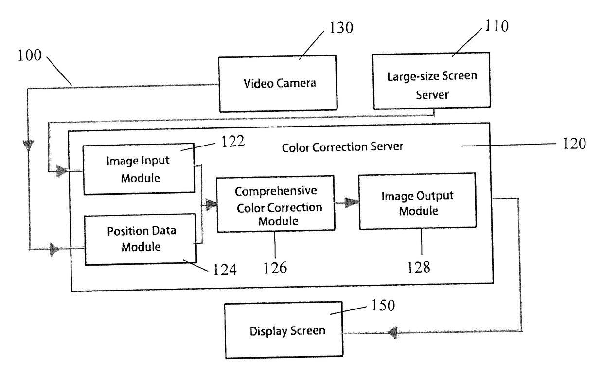
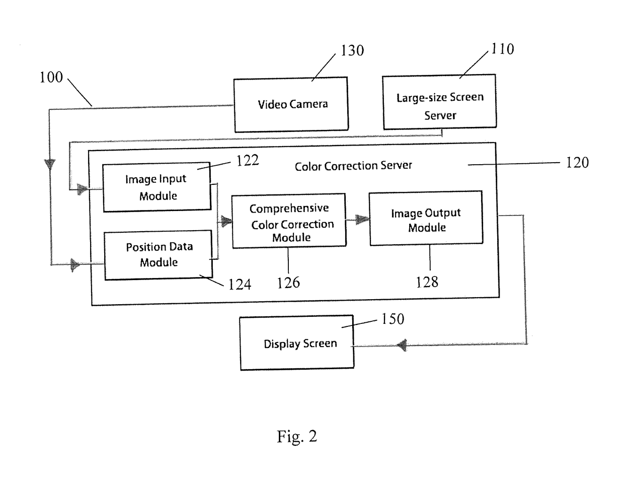
[0088]Overall unified pictures can be presented by recognizing the shooting position of the video camera and the parameters related to the cameras and combining real-time color correction software to set the parameters. The output color parameters are related to each screen in real time to adjust the display effect, so as to achieve a unified viewing effect from any angle, presenting overally unified pictures whether it be for an audience to watch or for program shooting.

[0089]Specifically, a mechanical sensor is adopted with grating coding to recognize the position of the video camera and the camera lens parameters. The related parameters of the video camera are gathered and sent to color correction software. The color correction software sets color configuration parameters of the video camera when in different positions in real-time, and connects and matches the parameters of the video camera with the parameters of the sensor. The color correction software uses related algorithms ...


PUM


Abstract

A method and system for a displaying contents that makes LED real-time 3D displays possible. The 3D image formation includes multi-screen display color correction and multi-camera infrared positioning technology. The present invention presents the display effects of a simulation environment in a better way through switching and moving and ensures that while in movement, the display effects of LED screens taken by video cameras from different angles can be maintained the same, so as to create a vivid simulation environment for television programming and film shooting.

Description

FIELD OF TECHNOLOGY[0001]This invention relates to a 3D image-formation system, more specifically a system and method used for LED display including multi-screen display color correction and multi camera infrared positioning technology.BACKGROUND[0002]LED large-size screens are extensively utilized in programming, display and advertising. But when utilized, multiple LED screens can have different in viewing angles, positions and directions, and style and dot spacing. When using a video camera to shoot, there will be chromatic aberration, leading to the failed integration of the viewing display effect with the display effect after shooting, as they have evident differences in boundary lines and brightness and darkness. Not all the screens can have the same shooting effects. And the color adjustment of the current LED screens in the market uses a pre-set fixed value, which cannot be matched or adjusted dynamically while in the shooting process.[0003]An LED display is realized by the p...

Claims


Application Information

Patent Timeline
IPC IPC(8): G06F3/14H04N13/00H04N13/02G06F3/01H04N5/33
CPCG06F3/1446H04N13/0025H04N13/0275G06F3/011H04N13/0282H04N5/33G06F3/1423G06F3/147G09G5/02H04N13/324H04N13/327H04N13/133H04N23/20H04N13/275H04N13/282
Inventor CHANG, JIANGLIU, XINGCHEN
Owner CHANG JIANG
Why Eureka
Eureka Blog
Learn More