Electrically driven device

a technology of electric motors and drives, applied in mechanical energy handling, mechanical equipment, mechanical energy handling, etc., can solve problems such as increased sound emissions

Active Publication Date: 2018-03-29
BRAUN GMBH
View PDF1 Cites 6 Cited by
  • Summary
  • Abstract
  • Description
  • Claims
  • Application Information

AI Technical Summary

Problems solved by technology

The use of gearwheels may contribute to increased sound emissions.

Method used


Image

  • Electrically driven device
  • Electrically driven device
  • Electrically driven device

Examples


Embodiment Construction

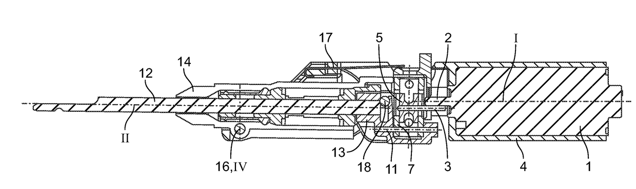
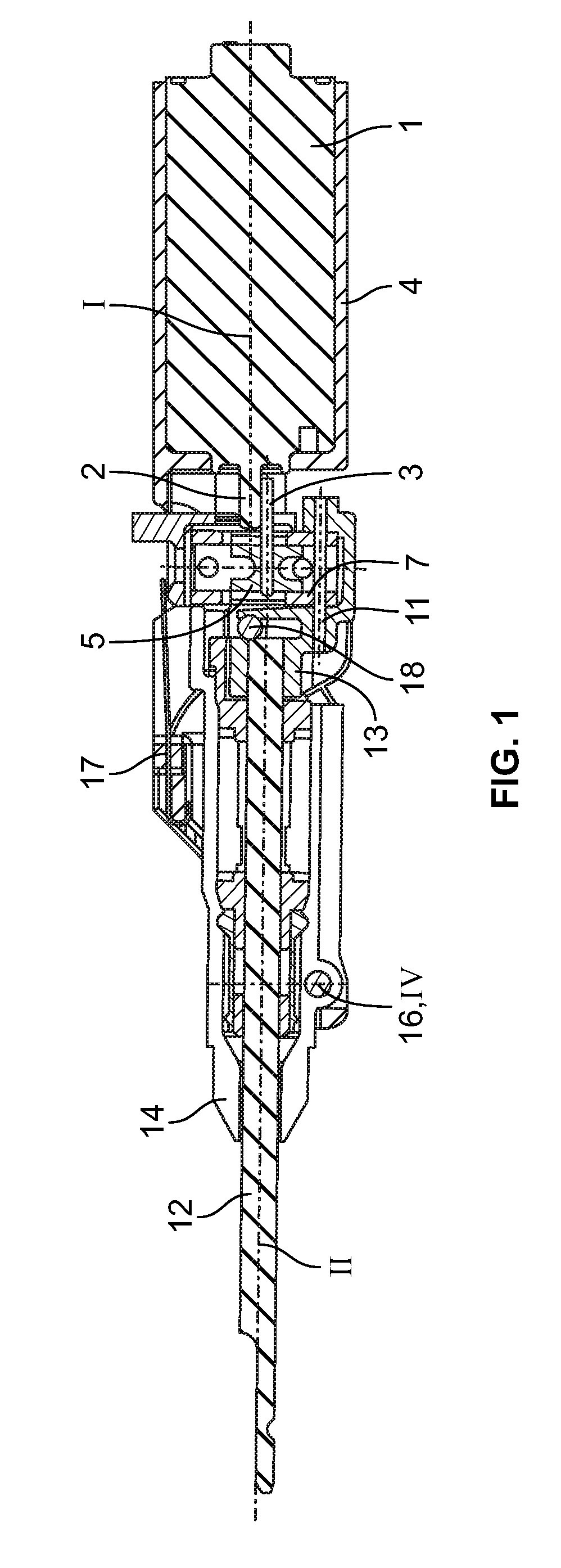
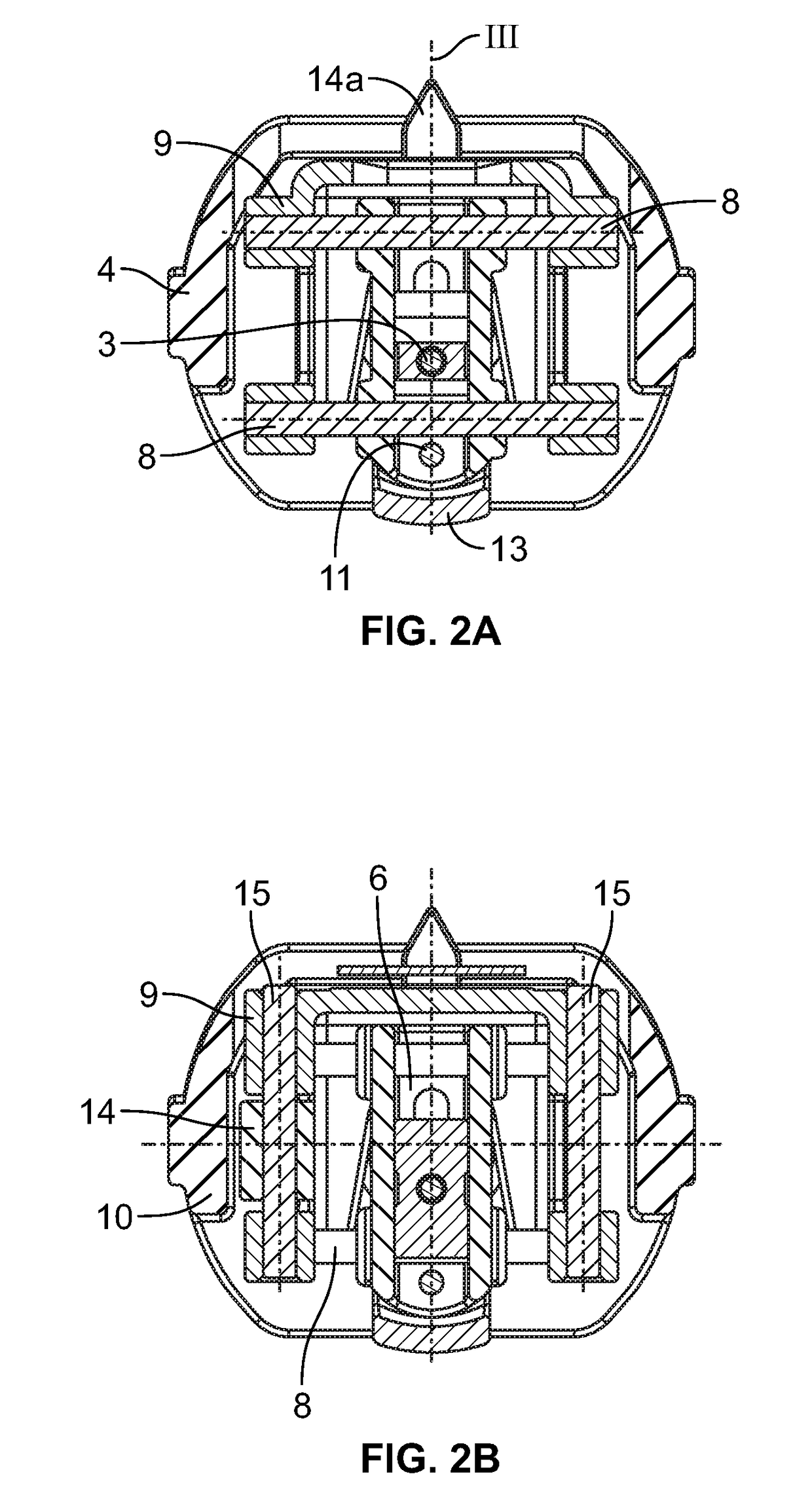
[0014]Current toothbrush drive systems performing an oscillating pivoting of the cleaning element, e.g. a bristle, are perceived as being too loud. In particular, it is desirable to provide an electrically driven device with sound emissions below 55 dB(A) sound power level, especially at current drive frequency of 83 Hz. An important factor for noise is the form of the motion over time. The velocity is the first derivative of the displacement, the acceleration the second derivative of the motion. Higher accelerations and therefore inertia forces occur if the wave form is not a sine wave or harmonic. These periodic forces translate into bearing reaction forces and thus create an excitation to the structure of the device and this can cause undesired noise of elements oscillating in their natural frequency. Another source of noise is two bodies hitting each other and creating a rattling noise. This occurs for example in cam driven systems.

[0015]According to an aspect, the gear mechanis...


PUM


Abstract

An electrically driven device includes an electric motor with a drive shaft having a first rotary axis and a drive pin eccentrically thereto, and a driven shaft having a second rotary axis and mounted for pivoting motion. The driven shaft is coupled to the drive shaft by a scotch yoke mechanism, converting a rotary motion of the drive shaft into a reciprocating pivoting motion of the driven shaft. The scotch yoke mechanism includes a cross slider having a sliding support extending perpendicular to the first rotary axis and receiving the drive pin either directly or by a sliding block having a bearing receiving the pin. The cross slider is axially guided to move in an axial direction perpendicular to the first rotary axis and to the extension of the sliding support. The driven shaft is coupled to the cross slider by a pivotable crank arm, thereby converting a rotary motion of the drive shaft into a reciprocating motion of the driven shaft.

Description

FIELD OF THE INVENTION[0001]The present invention is concerned with an electrically driven device, for example an electric toothbrush, an electric hair removal device or an electric skin treatment device.BACKGROUND OF THE INVENTION[0002]An electric toothbrush with a drive mechanism comprising gearwheels is known for example from DE 39 37 854 A1. The drive mechanism converts a continuous rotary movement of the drive shaft of an electric motor into a reciprocating pivoting of a driven shaft. EP 0 850 027 B1 and EP 1 357 854 B1 disclose further drive mechanisms with gearwheels wherein the mechanisms further generate an additional pivoting of the drive shaft about a swiveling axis. The use of gearwheels may contribute to increased sound emissions.[0003]US 2006 / 0101598 A1 discloses an electric toothbrush with a scotch yoke mechanism converting a continuous rotary movement of the drive shaft of an electric motor into a reciprocating longitudinal displacement of a driven shaft.[0004]Furthe...

Claims


Application Information

Patent Timeline
Patent Type & Authority Applications(United States)
IPC IPC(8): H02K7/075A45D26/00A61C17/34
CPCH02K7/075A45D26/00A61C17/3409A45D2026/008A61C17/3418A61C17/3454A61C17/3472F16H21/40A61C17/3436
Inventor FRITSCH Thomas (NMN)KRAMP Andreas (NMN)SCHAEFER Norbert (NMN)
Owner BRAUN GMBH
Why Eureka
Try Eureka