Electric caliper brake

a technology of caliper brake and caliper plate, which is applied in the direction of brake types, actuators, brake elements, etc., can solve the problems of increasing the required amount of brake oil for braking, adversely affecting the fuel economy of the vehicle, and difficult processing, so as to improve the operating efficiency

Active Publication Date: 2018-04-05
HL MANDO CORP
View PDF2 Cites 5 Cited by
  • Summary
  • Abstract
  • Description
  • Claims
  • Application Information

AI Technical Summary

Benefits of technology

[0012]Therefore, it is an aspect of the present disclosure to provide an electric caliper brake which enhances the operating efficiency.

Problems solved by technology

In particular, since the conventional spindle is formed of a steel material, the increased weight exerts a large load on the caliper housing, adversely affecting the fuel economy of the vehicle.
Further, since the protrusion portion must be formed through a cutting process, there is a problem that processing is difficult.
However, in the conventional electric caliper brake, there is a predetermined space between the piston and the spindle, for example, in a cylinder receiving a braking oil pressure, which increases the required amount of brake oil for braking, thereby reducing the feeling of braking.
At this time, a stuck occurs when the nut member is excessively close to the spindle member.
This problem is caused by the retraction of the nut member up to the threaded portion of the spindle member or by the clearance or wear of the manufacturing process.
However, occasionally, the stopper does not operate normally when the thread dimension is unstable or the stopper is damaged due to abrasion or impact.

Method used


Image

  • Electric caliper brake
  • Electric caliper brake
  • Electric caliper brake

Examples


Embodiment Construction

[0043]Hereinafter, the embodiments of the present disclosure will be described in detail with reference to the accompanying drawings. The following embodiments are provided to fully convey the spirit of the present disclosure to a person having ordinary skill in the art to which the present disclosure belongs. The present disclosure is not limited to the embodiments shown herein but may be embodied in other forms. For the sake of clarity, the drawings are not drawn to scale, and the size of the components may be slightly exaggerated to facilitate understanding.

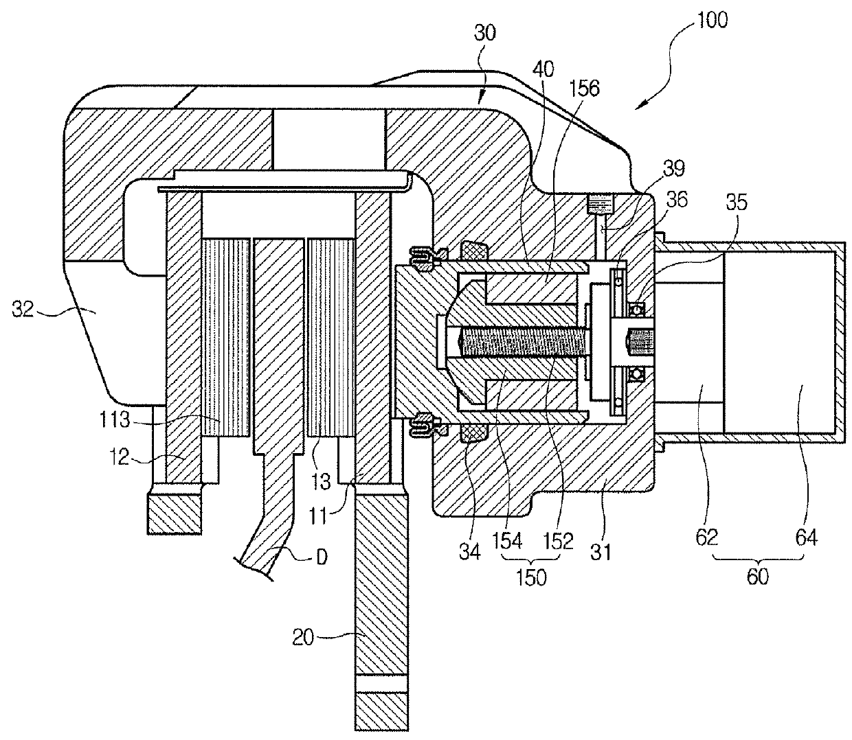
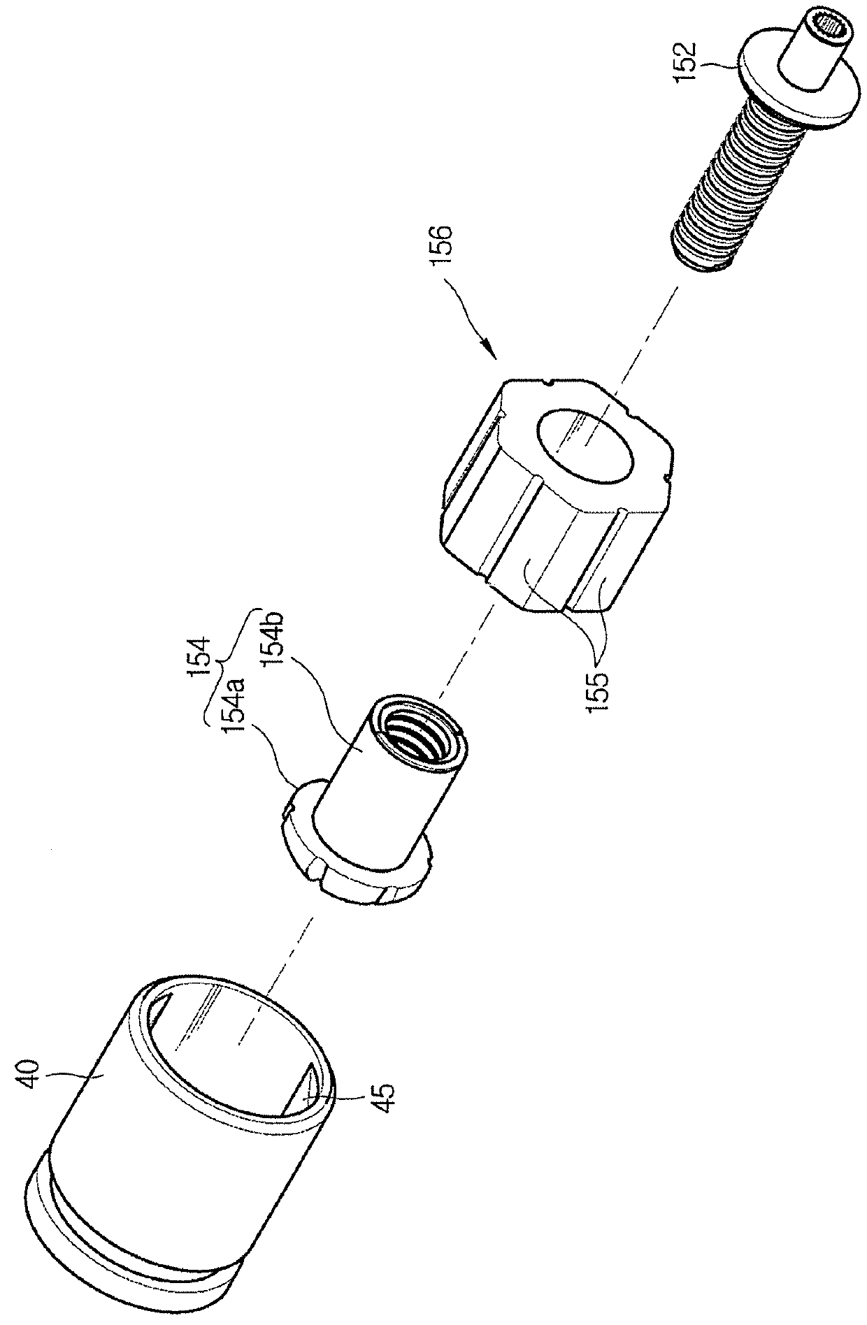
[0044]FIG. 1 is a cross-sectional view schematically showing an electric caliper brake according to an embodiment of the present disclosure, and FIG. 2 is an exploded perspective view showing a combined state of a piston, a power converting unit, and an anti-rotation member provided in the electric caliper brake.

[0045]As shown in FIGS. 1 and 2, an electric caliper brake 100 according to the present embodiment includes a carrie...


PUM


Abstract

Disclosed herein is an electric caliper brake. The electric caliper brake which includes a carrier provided with a pair of pad plates movably with respect to a disk, and a caliper housing slidably installed on the carrier and provided with a cylinder in which a piston is movably provided by braking oil pressure, includes a spindle member which is installed to penetrate a rear portion of the cylinder and rotates by receiving a rotational force from an actuator, and a power converting unit including a nut member which is screwed with the spindle member and is disposed in the piston, moves forward and backward in accordance with the rotation of the spindle member so as to press the piston; a filling member coupled to the nut member in the piston; and an anti-rotation surface provided on at least one plane on an outer circumferential surface of the filling member so that the filling member is coupled to the piston in a limited rotation state.

Description

CROSS-REFERENCE TO RELATED APPLICATION(S)[0001]This application claims priority to and the benefit of Korean Patent Application No. P2016-0072467, filed on Jun. 10, 2016 and P2016-0082539, filed on Jun. 30, 2016 in the Korean Intellectual Property Office, the disclosure of which is incorporated by reference in its entirety.BACKGROUND1. Technical Field[0002]The present disclosure relates to an electric caliper brake, and more particularly, to an electric caliper brake capable of simplifying a structure and improving operating efficiency.2. Description of the Related Art[0003]In general, an electric caliper brake is a device obtained by incorporating conventional hydraulic disk brakes into actuators that are electrically operated.[0004]Korean Patent Publication No. 10-2011-0124817 discloses an example of such an electric disk brake (hereinafter, referred to as an electric caliper brake). According to the disclosed document, the electric caliper brake includes a disk rotating together ...

Claims


Application Information

Patent Timeline
Patent Type & Authority Applications(United States)
IPC IPC(8): F16D65/18F16D65/00F16D55/226
CPCF16D65/18F16D65/0068F16D55/226F16D2121/04F16D2121/24F16D2125/40
Inventor KIM, KYUNG-WON
Owner HL MANDO CORP
Why Eureka
Try Eureka