Arc Detection and Prevention in a Power Generation System
Active Publication Date: 2018-04-05
SOLAREDGE TECH LTD
View PDF10 Cites 14 Cited by
Summary
Abstract
Description
Claims
Application Information
AI Technical Summary
This helps you quickly interpret patents by identifying the three key elements:
Problems solved by technology
Method used
Benefits of technology
[0017]In some embodiments, photovoltaic power devices may feature multiple output voltage terminals. In some embodiments, photovoltaic generators and photovoltaic power devices may be coupled together and/or may be arranged to provide a plurality of lower-impedance voltage loops. Designing photovoltaic string to have lower-impedance voltage
Problems solved by technology
Arcing may occur in switches, circuit breakers, relay contacts, fuses and poor cable terminations.
If a circuit has enough current and voltage to sustain an arc, the arc can cause damage to equipment such as melting of conductors, destruction of insulation, and fire.
A direct current system may be more prone to arcing than AC systems because of the absence of zero crossing in DC power systems.
Electric arcing can have detrimental effects on electric power distribution systems and electronic equipment, and in particular, photovoltaic systems, which are often arranged in a manner that increases the risk of arching.
For example, photovoltaic panels often op
Method used
Image
Click on the blue label to locate the original text in one second.
Reading with bidirectional positioning of images and text.
Examples
Embodiment Construction
[0045]Reference will now be made in detail to embodiments, examples of which are illustrated in the accompanying drawings, wherein like reference numerals refer to the like elements throughout. The embodiments are described below to explain the present disclosure by referring to the figures.
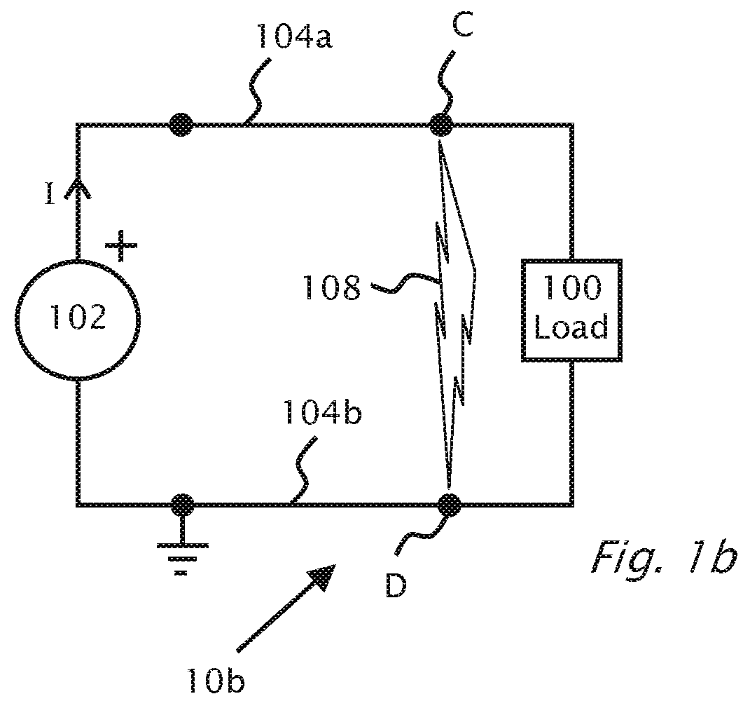
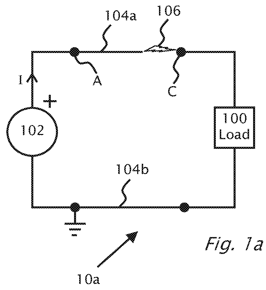
[0046]Reference is made to FIG. 1a which shows serial arcing 106 in a circuit 10a according to background art. In FIG. 1a, a direct current (DC) power supply 102 provides power between power lines 104a and 104b. Power line 104b is shown at ground potential. Load 100 connects power line 104b to power line 104a. Serial arcing may occur in any part of circuit 10a in power lines 104a, 104b or internally in load 100 or supply 102 for example. A disconnection or poor connection in power line 104a between point C and point A is shown which causes an instance 106 of serial arcing. Typically, if series arc 106 can be detected, circuit breakers (not shown) located at supply 102 or load 100 can be tripped t...
PUM
Abstract
Methods for arc detection in a system including one or more photovoltaic generators, one or more photovoltaic power devices and a system power device and/or a load connectible to the photovoltaic generators and/or the photovoltaic power devices. The methods may measure voltage, current, and/or power delivered to the load or system power device, and the methods may measure voltage noise or current noise within the photovoltaic system. The methods may periodically, and/or in response to detecting noise, reduce an electrical parameter such as current or voltage in order to extinguish an arc. The methods may compare one or more measurements to one or more thresholds to detect arcing, and upon a comparison indicating that arcing is or was present, an alarm condition may be set.
Description
CROSS REFERENCE TO RELATED APPLICATIONS[0001]The present application is a continuation-in-part (CIP) application of U.S. application Ser. No. 15 / 407,881. filed Jan. 17, 2017, which is a continuation-in-part (CIP) application of U.S. application Ser. No. 13 / 290,528, filed Nov. 7, 2011, which claims priority to United Kingdom Application GB1018872.0, filed Nov. 9, 2010, all of which are incorporated herein by reference in their entirety. U.S. application Ser. No. 15 / 407,881 is also a continuation-in-part (CIP) application of U.S. application Ser. No. 15 / 250,068, filed Aug. 29, 2016, which claims priority to U.S. provisional patent Application Ser. No. 62 / 318,303, filed Apr. 5, 2016 and to U.S. provisional patent Application Ser. No. 62 / 341,147, filed May 25, 2016, all of which are incorporated herein by reference in their entirety. U.S. application Ser. No. 15 / 407,881 also claims priority to U.S. provisional patent Application Ser. No. 62 / 395,461, filed Sep. 16, 2016, which is incorpo...
Claims
Application Information
Patent Timeline
Application Date:The date an application was filed.
Publication Date:The date a patent or application was officially published.
First Publication Date:The earliest publication date of a patent with the same application number.
Issue Date:Publication date of the patent grant document.
PCT Entry Date:The Entry date of PCT National Phase.
Estimated Expiry Date:The statutory expiry date of a patent right according to the Patent Law, and it is the longest term of protection that the patent right can achieve without the termination of the patent right due to other reasons(Term extension factor has been taken into account ).
Invalid Date:Actual expiry date is based on effective date or publication date of legal transaction data of invalid patent.