Data buffering control system and method for a communication network

a control system and communication network technology, applied in the field of data buffering control system and communication network, can solve the problems of endpoint delay or latency, adversely affecting content delivery to some or all of the users, frequent closing of the tcp receive window,

Active Publication Date: 2018-04-05
HUGHES NETWORK SYST
View PDF2 Cites 6 Cited by
  • Summary
  • Abstract
  • Description
  • Claims
  • Application Information

AI Technical Summary

Benefits of technology

[0008]Accordingly, exemplary embodiments of the present invention provide a data buffering control system and method for a communication network that employ a buffer disposed at a destination site and a controller. The buffer is configured to buffer data received at a data receiving rate by the destination site for delivery by the destination site to a user at a delivery flow rate. The controller is configured to increase or decrease a buffering rate according to which t

Problems solved by technology

In communication networks, such as satellite-based communication networks, endpoint delay or latency is an ongoing concern.
Thus, the different users may experience different performance which may adversely affect content delivery to some or all of the users.
Although the known types of proxy mechanisms discussed above may be beneficial in improving endpoint performance in certain scenarios, proxy mechanisms often create other issues relating, in particular, to buffer usage at the proxy server.
For example, limited memory on an end-user device, such as a Smart TV, can cause frequent closing of the TCP receive window.
Hence, the use of, for example, a Netflix App on a Smart TV with limited memory may result in frequent closing of the TCP receive window.
Also, an application

Method used


Image

  • Data buffering control system and method for a communication network
  • Data buffering control system and method for a communication network
  • Data buffering control system and method for a communication network

Examples


Embodiment Construction

[0026]Selected embodiments will now be explained with reference to the drawings. It will be apparent to those skilled in the art from this disclosure that the following descriptions of the embodiments are provided for illustration only and not for the purpose of limiting the invention as defined by the appended claims and their equivalents.

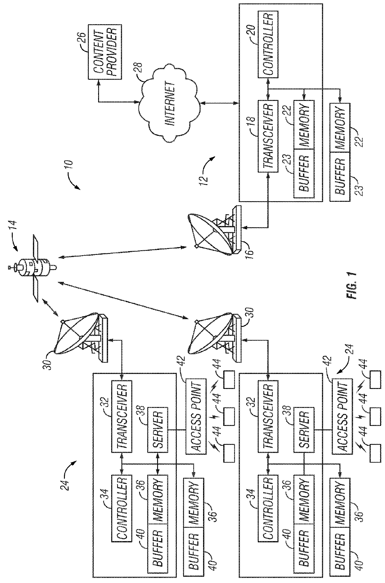
[0027]FIG. 1 illustrates an example of a satellite communication network 10 according to an exemplary embodiment. A satellite communication network 10 typically includes a plurality of terrestrially mounted gateways 12 that communicate with one or more orbiting satellites 14. Each satellite gateway includes an antenna dish 16, a transceiver 18, a controller 20, a memory 22 and other types of equipment (not shown) such as amplifiers, waveguides and so on as understood in the art on which enable communication between the gateway 12 and a plurality of terminals 24 via one or more of the orbiting satellites 14. The memory 22 can be, for example, an in...


PUM


Abstract

A data buffering control system and method for a communication network comprises a buffer disposed at a destination site, and a controller. The buffer is configured to buffer data received at a data receiving rate by the destination site for delivery by the destination site to a user at a delivery flow rate. The controller is configured to increase or decrease a buffering rate according to which the data is buffered in the buffer based on an amount of buffered data in the buffer without stopping the buffering of the data in the buffer. The controller is configured to perform a transmission control protocol spoofing process at the destination site to effect a communication handshaking operation, without the destination site communicating with a source providing the data, to control the data receiving rate by the destination site, to thus modify the buffering rate.

Description

BACKGROUNDField of the Invention[0001]The present invention generally relates to a data buffering control system and method for a communication network and, in particular, for a satellite-based communication network. More specifically, the present invention relates to a data buffering control system and method for a satellite-based communication network that controls a buffering rate according to which data received by a destination site, such as an end-user terminal or an end-user device, is buffered in a buffer at the destination site based on an amount of buffered data in the buffer without stopping the buffering of the data in the buffer.Background Information[0002]In communication networks, such as satellite-based communication networks, endpoint delay or latency is an ongoing concern. For example, in a residential setting, several users are often accessing content at the same time via the wireless local area network (WLAN) at the residence. One user may be attempting to stream...

Claims


Application Information

Patent Timeline
IPC IPC(8): H04L12/835H04L12/825H04B7/185H04L47/30H04L47/40
CPCH04L47/30H04B7/18513H04L47/25H04L47/40H04L47/263H04W28/0205H04W28/0273H04W8/04
Inventor TORRES, ROBERT JAMESJAVALI, NAGESHGANESAN, VENKAT
Owner HUGHES NETWORK SYST
Why Eureka
Try Eureka