Eureka AIR delivers breakthrough ideas for toughest innovation challenges, trusted by R&D personnel around the world.

Method and Apparatus For Vehicle Inspection and Safety System Calibration Using Projected Images

a technology for safety systems and vehicles, applied in the direction of picture reproducers using projection devices, using reradiation, instruments, etc., can solve problems such as failure to detect or properly, data acquired may not be accurate, and insufficient identification

Active Publication Date: 2018-04-12
HUNTER ENG
View PDF0 Cites 33 Cited by
  • Summary
  • Abstract
  • Description
  • Claims
  • Application Information

AI Technical Summary

Benefits of technology

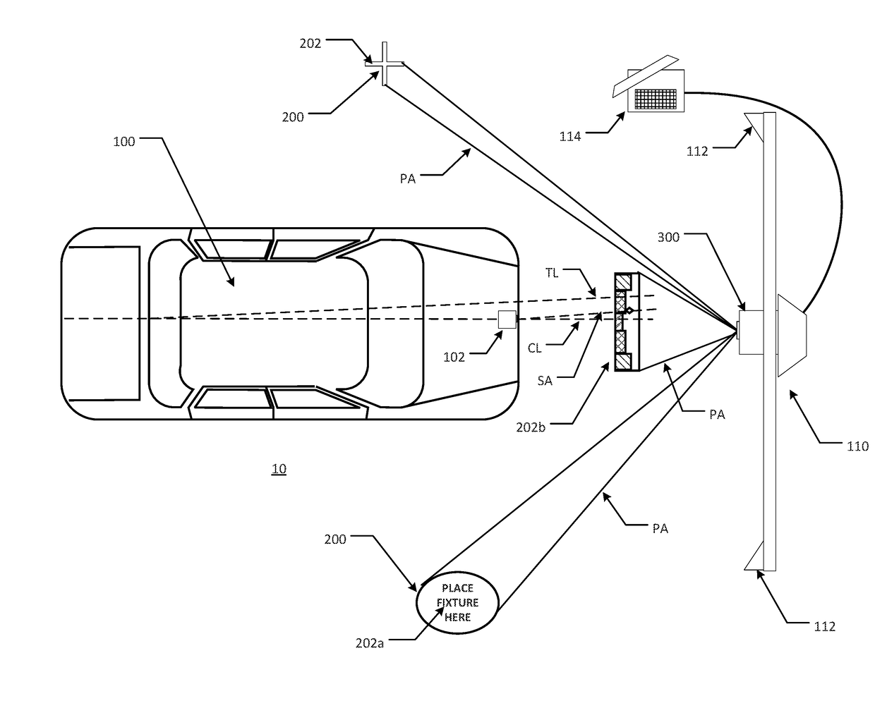
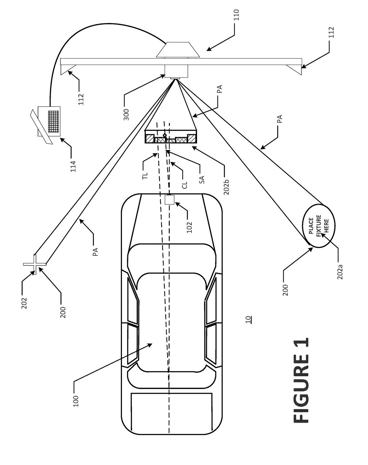
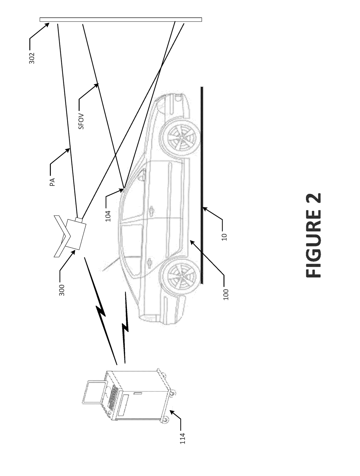
The present patent is for a vehicle service system that includes an optical projector and an optical video camera, as well as an optical laser beam for precise measurements. The system can project markings onto a floor surface in proximity to the vehicle to identify specific locations where safety system sensors should be placed for observation. The system can also use a radar emitter to simulate the movement of objects within a field of view of the vehicle's radar system. The processor controls the optical projector and radar emitter to interface with the vehicle's control system and sensors to determine if they are responding as expected to the simulated test drive conditions. The technical effects include improved safety and efficiency during vehicle service procedures.

Problems solved by technology

If a sensor is misaligned, data acquired may not represent the presence of an object which is adjacent to, or approaching the vehicle, or may be insufficient to identify the location of observed objects.
Failure to detect or properly identify observed objects may lead to situations in which warnings are not provided by the vehicle, and corrective actions are not taken, or alternatively, to situations in which warnings or corrective action are provided or taken in error.
Failure of such an onboard vehicle system to properly detect and locate objects in the vicinity of the vehicle could lead to collisions between the vehicle and the object.

Method used


Image

  • Method and Apparatus For Vehicle Inspection and Safety System Calibration Using Projected Images
  • Method and Apparatus For Vehicle Inspection and Safety System Calibration Using Projected Images
  • Method and Apparatus For Vehicle Inspection and Safety System Calibration Using Projected Images

Examples


Embodiment Construction

[0020]The following detailed description illustrates the invention by way of example and not by way of limitation. The description enables one skilled in the art to make and use the present disclosure, and describes several embodiments, adaptations, variations, alternatives, and uses of the present disclosure, including what is presently believed to be the best mode of carrying out the present disclosure.

[0021]Procedures of the present disclosure for facilitating, during a vehicle service or inspection, the alignment and calibration of vehicle onboard sensors which monitor or observe the external environment surrounding the vehicle, such as radar, LIDAR, infrared, or optical sensors used for blind spot monitoring, cross-traffic monitoring, lane departure warnings, collision avoidance systems, and automatic cruise control, are illustrated with reference to the accompanying illustrations. It will be understood by those of ordinary skill in the art that these procedures are intended to...


PUM


Abstract

A vehicle service system and method to determine spatial parameters of a vehicle, employing a display system under processor control, to display or project visible indicia onto surfaces in proximity to a vehicle undergoing a safety system service or inspection identifying one or more locations, relative to the determined vehicle centerline or thrust line, at which a calibration fixture, optical target, or simulated test drive imagery is visible for observation by a sensor onboard the vehicle.

Description

CROSS-REFERENCE TO RELATED APPLICATIONS[0001]The present application is related to, and claims priority from, U.S. Provisional Patent Application Ser. No. 62 / 406,679 filed on Oct. 11, 2016, which is herein incorporated by reference.STATEMENT REGARDING FEDERALLY SPONSORED RESEARCH[0002]Not Applicable.BACKGROUND OF THE INVENTION[0003]The present application is related to systems and methods for the inspection and calibration of vehicle safety systems, and in particular, to vehicle service equipment configured to utilize at least one projector to emit electromagnetic energy during a vehicle safety system inspection or calibration procedure, aiding the placement of a vehicle service fixture relative to the vehicle, or providing vehicle onboard sensors with signal input simulating, to sensors onboard the vehicle, at least a portion of a test drive scenario.[0004]Within the automotive industry there are an increasing number of vehicle manufacturers producing vehicles equipped with onboard...

Claims


Application Information

Patent Timeline
Patent Type & Authority Applications(United States)
IPC IPC(8): G01M17/007G07C5/08G01S7/40H04N9/31
CPCG01M17/007G07C5/0808G07C5/0816G01S7/40H04N9/315G01S13/931G01S2013/9332G01S7/497G01S17/936G01S13/867G01S2013/9353G01S7/4026G01S7/4052H04N9/3179H04N9/3185H04N9/3194G01S17/931G01B11/2755G01B11/2545G01S7/4086G01S2013/932G01S2013/9315
Inventor STIEFF, MICHAEL T.STREGE, TIMOTHY A.
Owner HUNTER ENG
Why Eureka
Eureka Blog
Learn More