
High-precision autonomous obstacle-avoidance flying method for unmanned aerial vehicle

an unmanned aerial vehicle and flying method technology, applied in vehicle position/course/altitude control, process and machine control, instruments, etc., can solve the problems of low operation efficiency, high labor cost, and inability to realize long-distance high-precision flight, so as to improve positioning precision and weight. the effect of heavy weigh

Inactive Publication Date: 2018-04-12
CAO FEI
View PDF2 Cites 17 Cited by
  • Summary
  • Abstract
  • Description
  • Claims
  • Application Information

AI Technical Summary

Benefits of technology

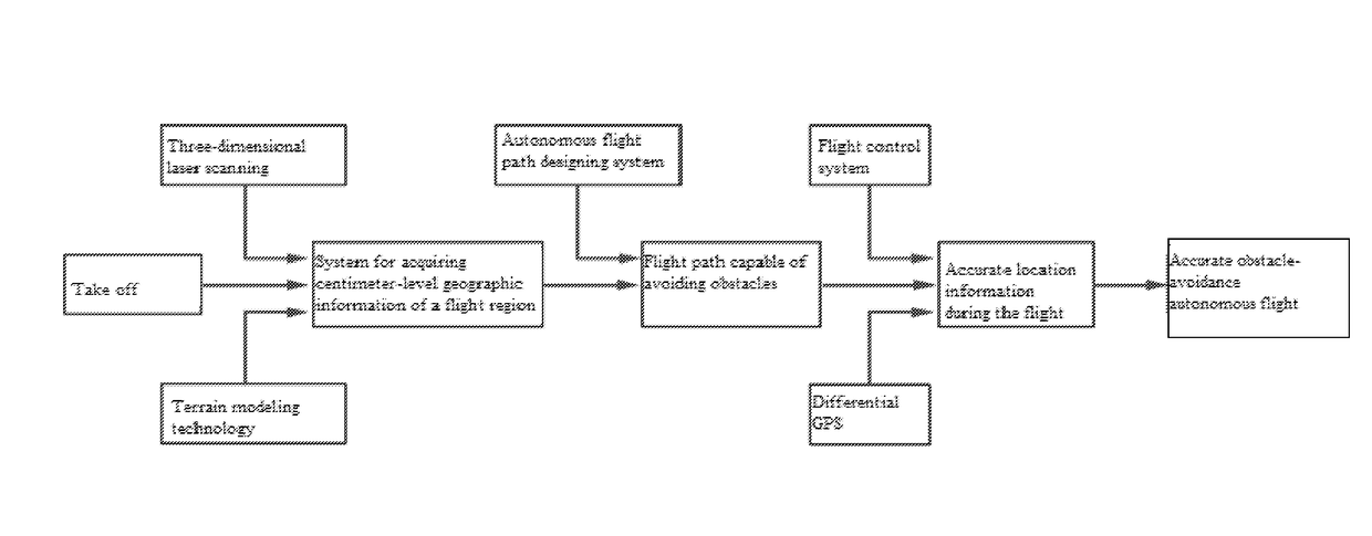
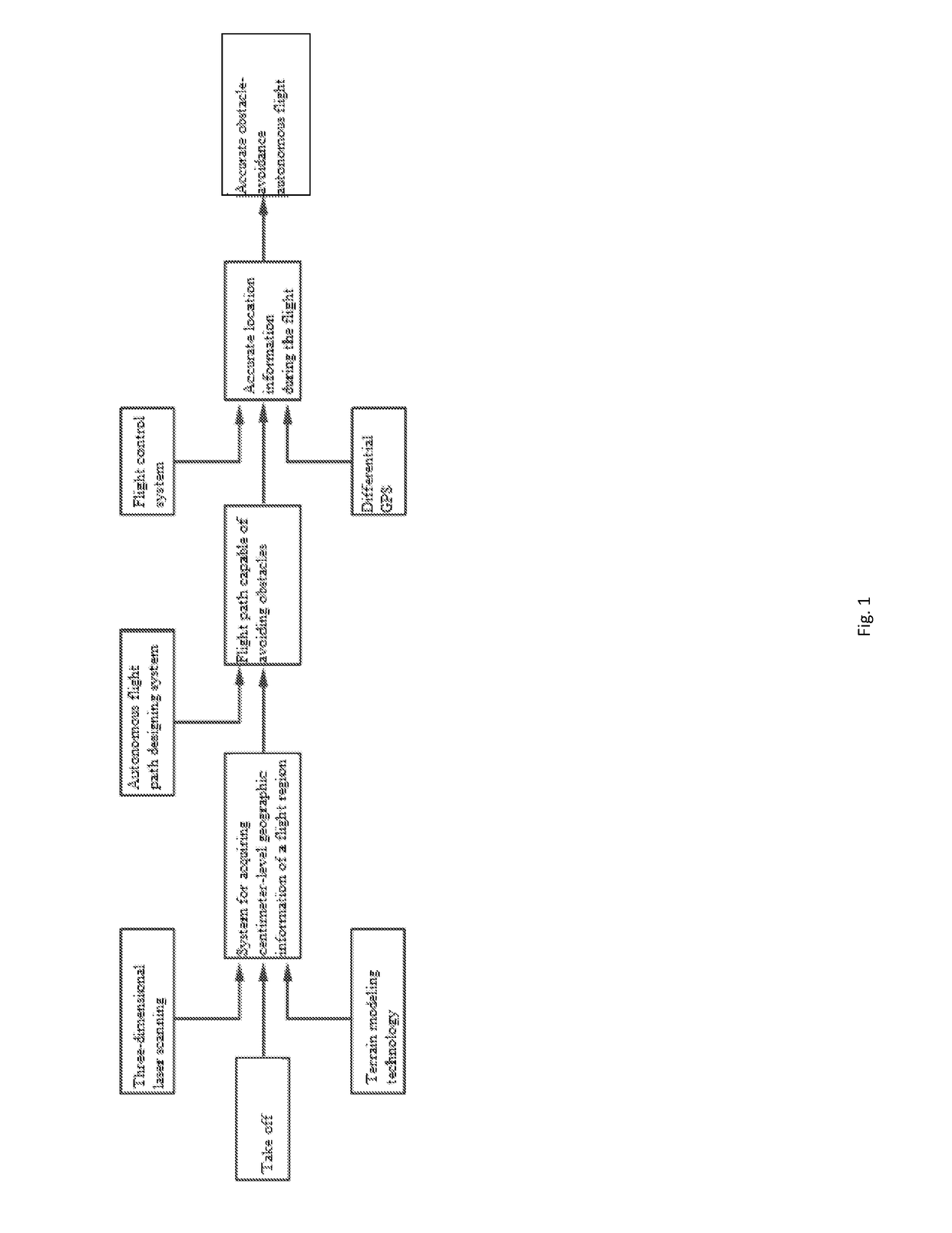
The present invention is a high-precision autonomous obstacle-avoidance flying method for unmanned aerial vehicles. It has the following technical effects: 1. Accurate planning of the flight path through a high-precision three-dimensional map model of a human-computer interaction interface. 2. The use of micro differential GPS and laser scanning technology to acquire accurate space coordinates of the destination flight region and support autonomous obstacle-avoidance flight path planning. 3. Feedback of real-time location information to the flight control system through a high-precision micro differential GPS module, allowing for accurate space location acquisition and centimeter-level location control. 4. Automatic avoidance of obstacles along the pre-planned path, ensuring unmanned aerial vehicle safety and efficiency in executing work tasks.

Problems solved by technology

In low-altitude and complex terrain flight applications, because the existing satellite positioning precision is not enough and the UAV cannot know accurate location information, the full-autonomous flight mode cannot be adopted and the UAV only can be manually operated relying on ground control personnel to fly.
In this way, not only long-distance high-precision flight cannot be realized due to the limitation of a communication way, but also the skilled ground control personnel with rich experience is needed, so that the labor cost is high, the operation efficiency is low, and the increasing application demand on the UAV cannot be satisfied.
A traditional UAV cannot realize the high-precision autonomous obstacle avoidance, and can only realize the automatic flight at a high altitude away from obstacles and can only be manipulated by the control personnel with rich experience to assist the flight in a complex flight region close to the obstacles.

Method used


Image

  • High-precision autonomous obstacle-avoidance flying method for unmanned aerial vehicle
  • High-precision autonomous obstacle-avoidance flying method for unmanned aerial vehicle
  • High-precision autonomous obstacle-avoidance flying method for unmanned aerial vehicle

Examples


Embodiment Construction

[0037]The present invention is further described below in combination with embodiments and with reference to the attached drawings.

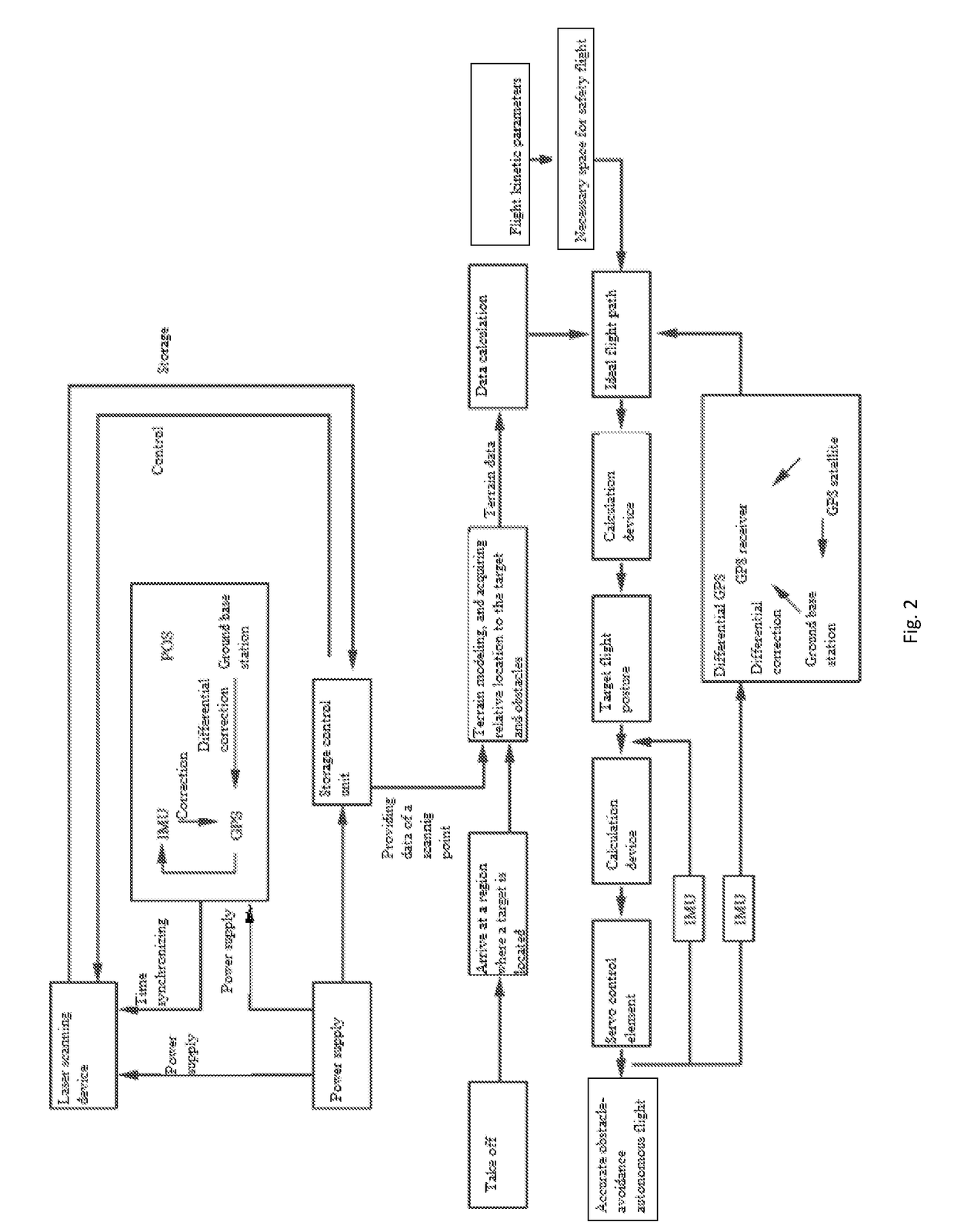
[0038]A high-precision autonomous obstacle-avoidance flying method for an unmanned aerial vehicle includes the following steps:

[0039](1) establishing a high-precision map model:

[0040]1.1) after a load operating device of the unmanned aerial vehicle arrives at a designated working region, acquiring, by a differential GPS system, an accurate space location of the unmanned aerial vehicle, and acquiring an accurate space coordinate of a laser scanning system according to a relative location of a known laser scanning system and the unmanned aerial vehicle, wherein the differential GPS system is realized by a micro differential GPS module;

[0041]1.2) acquiring, by an inertial navigation apparatus serving as a reference center of a whole laser radar system, a posture, and a coordinate location, meeting the accuracy requirement, of the unmanned aerial vehicle;

[00...


PUM


Abstract

The present invention relates to a high-precision autonomous obstacle-avoidance flying method for an unmanned aerial vehicle, which includes the following steps: (1) establishing a high-precision map model; (2) planning a three-dimensional flight path and controlling the flight; and (3) transmitting a flight control signal in step (2) to a steering engine of an aircraft servo mechanism of the unmanned aerial vehicle, thereby achieving a control purpose by changing a location of the steering engine.

Description

CROSS-REFERENCE TO RELATED APPLICATIONS[0001]This application is a continuation of International Patent Application No. PCT / CN2016 / 085497 with a filing date of Jun. 12, 2016, designating the United States, now pending, and further claims priority to Chinese Patent Application No. 201510320701.8 with a filing date of Jun. 12, 2015. The content of the aforementioned applications, including any intervening amendments thereto, are incorporated herein by reference.FIELD OF THE INVENTION[0002]The present invention relates to the field of navigation of unmanned aerial vehicles, and more particularly to a high-precision autonomous obstacle-avoidance flying method for an unmanned aerial vehicle.BACKGROUND OF THE INVENTION[0003]An unmanned aerial vehicle is abbreviated as “UAV” and is an unmanned aircraft manipulated by utilizing a radio remote control device and an autonomous program control apparatus. The UAV is widely used in the industries such as police, urban management, agriculture, ge...

Claims


Application Information

Patent Timeline
IPC IPC(8): G08G5/00G08G5/04
CPCG08G5/0069G08G5/0039G08G5/045G08G5/006B64C2201/141G08G5/0013G08G5/0034G05D1/106B64U2201/10
Inventor CAO, FEI
Owner CAO FEI
Learn More