System for Controlling Light and for Tracking Tools in a Three-Dimensional Space

a technology of three-dimensional space and light, applied in the field of system for supporting workflow, controlling light, and tracking and delivering objects in a three-dimensional space, can solve the problems of cumbersome conventional light booms, high operating costs, and high risk of light boom collisions, so as to avoid collisions and entanglement problems, improve efficiency, and save operating tim

Active Publication Date: 2018-04-26
DELSPINA BRANDON
View PDF0 Cites 12 Cited by
  • Summary
  • Abstract
  • Description
  • Claims
  • Application Information

AI Technical Summary

Benefits of technology

This patent describes a new system that uses multiple components to control and move different tools in a precise manner. These include an imaging module, an illumination module, and an object manipulator module. A cable robot module is used to move a vector camera around and change its perspective based on instructions from a central computer module. Overall, this system allows for better management of space and reduces the likelihood of collisions between tools.

Problems solved by technology

The technical problem addressed in this patent is how to improve the management of lighting and environment in operating theaters and other medical facilities where minimizing interruptions and ensuring proper alignment between surgical tools and patient targets are crucial factors for safe and effective procedures. Current methods require constant adjustment of lights and have limitations when trying to track moving parts like hands and heads. Additionally, current technology does not allow for easy identification and targeting of specific areas of concern within the operational setting.

Method used


Image

  • System for Controlling Light and for Tracking Tools in a Three-Dimensional Space
  • System for Controlling Light and for Tracking Tools in a Three-Dimensional Space
  • System for Controlling Light and for Tracking Tools in a Three-Dimensional Space

Examples


examples

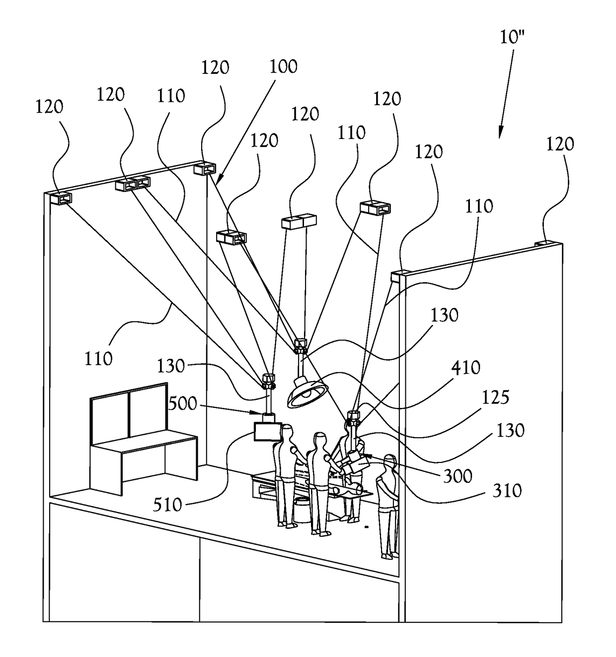
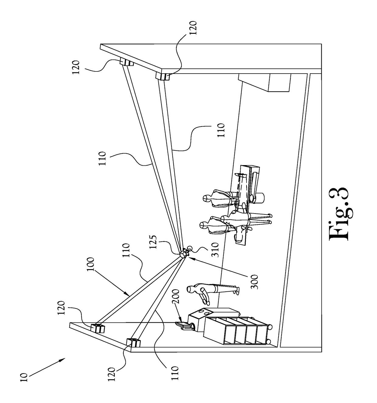
[0040]In an exemplary configuration of the system 10 of the present invention, composed of a cable robot module 100 composed of four cables 110 and four motor winch boxes 120, an infrared vector camera 310, remote foot controller, touchless temperature sensor and LED lamp. The central control computer module 200 receives inputs from the onboard vector camera 310 attached to the cable robot module 100. These inputs are composed of coordinate points providing the central computer 200 with adequate information to determine the location of markers in the X, Y, and Z planes of three-dimensional space, as well as their corresponding roll, pitch and yaw. Furthermore, these inputs consist of the signal strength received by the camera from the markers allowing for the central control computer to determine when the markers become outside of the field of view of the vector camera 310. When the markers become outside the field of view of the vector camera, a switch triggers in the central contr...


PUM


Abstract

A system adapted for supporting workflow in a three-dimensional space which provides, among other things, hands-free control and adjustment of lighting within the three-dimensional space. The system of the present invention is also adapted for delivering, tracking, and retrieving tools in the three-dimensional space. The system of the present invention includes various subsystems, which are referred to herein as modules, that both act independently and co-dependently, as will be described in greater detail below, in conjunction with a central control computer module. The modules consist, in an exemplary embodiment, of the cable robot module, the central computer module, the imaging module, the illumination module, and the object manipulator module.

Description


Claims


Application Information

Patent Timeline
Owner DELSPINA BRANDON
Why Eureka
Try Eureka