Work vehicle

a technology for working vehicles and steering valves, applied in the direction of mechanical control devices, manual control devices, instruments, etc., can solve the problems of extra work and inability to operate the steering control valve, and achieve the effect of less work

Active Publication Date: 2018-04-26
KOMATSU LTD
View PDF1 Cites 5 Cited by
  • Summary
  • Abstract
  • Description
  • Claims
  • Application Information

AI Technical Summary

Benefits of technology

[0007]In light of the above problem encountered in the past, it is an object of the present invention to provide a work vehicle that entails less work to leave the seat.
[0010]Thus, enough space for leaving the seat can be ensured by rotating the console box to the rear, and the hydraulic actuator can be locked, with both of these being accomplished with a single operation, so less work is entailed when the operator leaves his seat.
[0011]As the console box rotates, the link rod slides along the slot, rotating the opening and closing shaft and putting the shutoff valve in its closed position. Thus, the shutoff valve is put in a blocked state when the console box is rotated by a mechanical link, so the locking of the hydraulic actuator is accomplished easily.
[0016]Thus forming the slot in a linear shape results in less wear than when the slot has a curved shape.
[0019]Therefore, the shutoff valve spends as little time as possible between the blocked state and the opened state, switching between the two states can be carried out quickly, and the locked and unlocked states of the hydraulic actuator can be clearly distinguished.
[0022]Thus, providing the shutoff valve higher than the floor makes cab assembly easier than when the shutoff valve is provided lower than the floor.

Problems solved by technology

With a conventional configuration, however, when the operator leaves the operator's seat, the lock lever has to be rotated after the console box has been rotated to the rear, which entails extra work.
Thus blocking off the pilot fluid causes the steering control valve not to operate, so the hydraulic actuator is not driven and the steering is locked.

Method used


Image

  • Work vehicle
  • Work vehicle
  • Work vehicle

Examples


Embodiment Construction

[0053]The wheel loader of an exemplary embodiment pertaining to the present invention will now be described through reference to the drawings.

1. Configuration

[0054]1-1. Overview of Wheel Loader Configuration

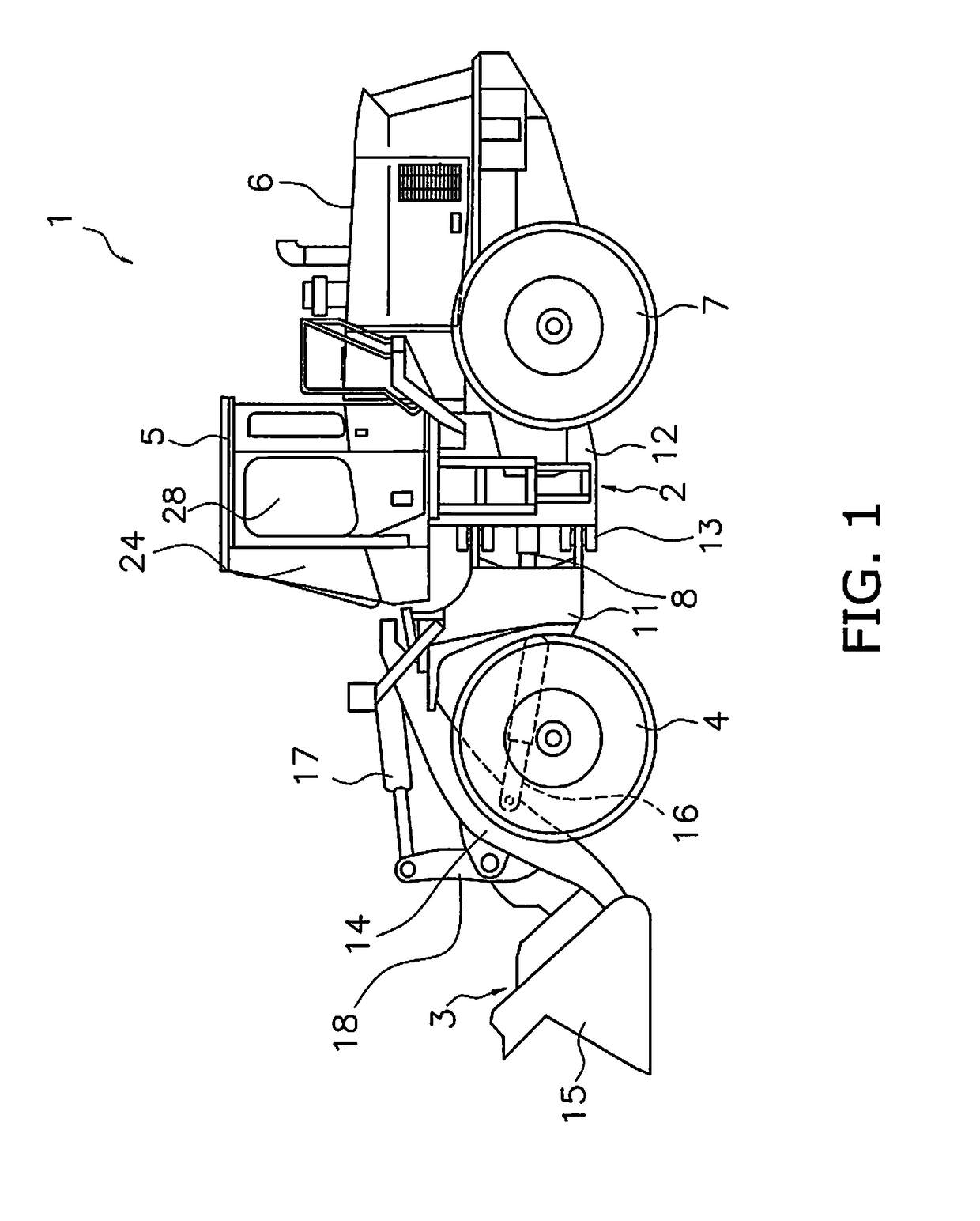
[0055]FIG. 1 is a simplified view of the configuration of a wheel loader 1 in this exemplary embodiment. The wheel loader 1 in this exemplary embodiment mainly comprises a body frame 2, a work implement 3, a pair of front tires 4, a cab 5, an engine compartment 6, a pair of rear tires 7, and an actuator drive-use hydraulic circuit 200 (FIG. 21).

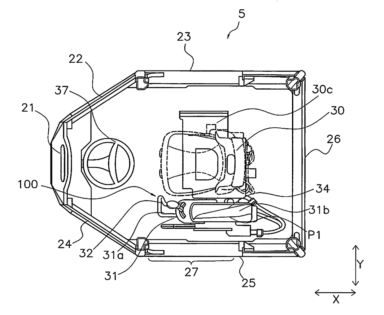
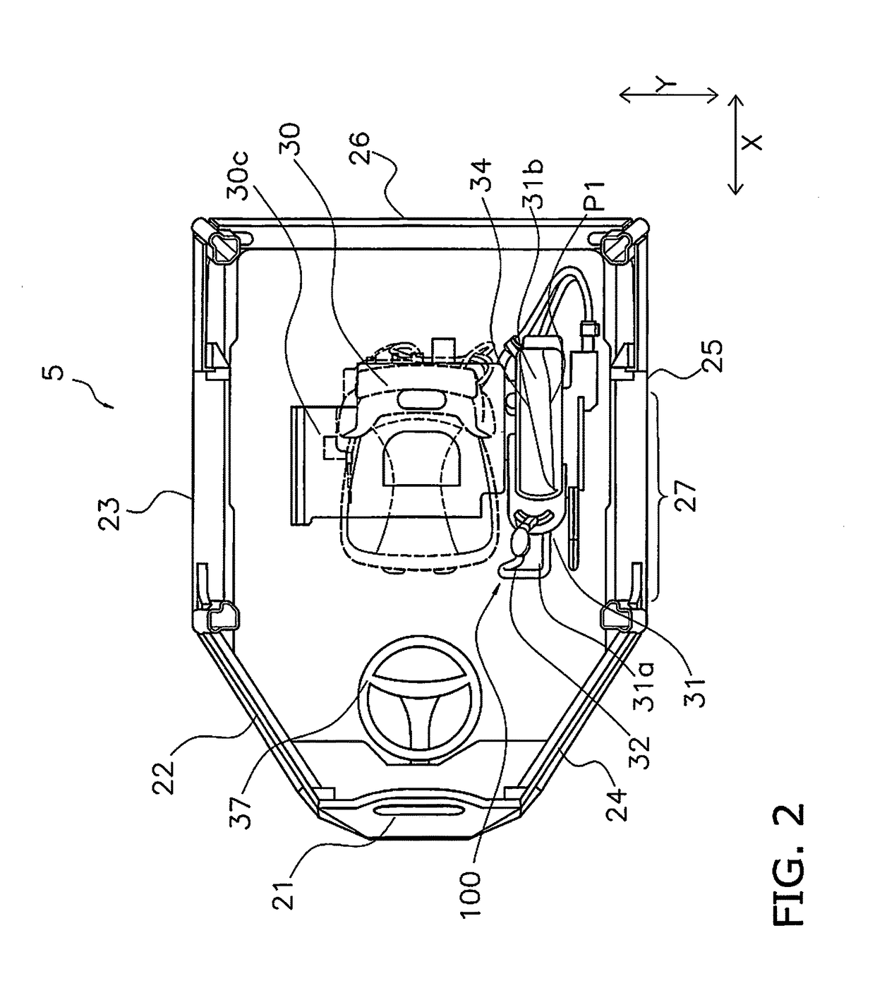
[0056]In this exemplary embodiment, the forward, rearward, left, and right directions refer to those directions as seen by an operator sitting in an operator's seat 30 (discussed below) inside the cab 5.

[0057]The wheel loader 1 uses the work implement 3 to perform work, such as scooping up soil.

[0058]The body frame 2 is an articulated type, and has a front frame 11, a rear frame 12, and a linking shaft 13. The front frame 11 is disposed ah...


PUM


Abstract

A wheel loader includes a console box, a link rod, and a shutoff valve. The console box is disposed on the side of an operator's seat, is able to rotate in the forward and backward direction between an operation position in which the console box is disposed horizontally and a retracted position in which the console box is rotated rearward from the operation position, and has a slot. The link rod is connected at one end to the slot and transmits the rotation of the console box. The link rod is able to rotate a shaft to switch between an open position in which an actuator drive-use hydraulic circuit can be actuated, and a closed position in which the actuator drive-use hydraulic circuit cannot be actuated. A second end of the link rod is linked to the shaft.

Description

CROSS-REFERENCE TO RELATED APPLICATIONS[0001]This application is a U.S. National stage application of International Application No. PCT / JP2016 / 081339, filed on Oct. 21, 2016.BACKGROUNDField of the Invention[0002]The present invention relates to a work vehicle.Description of the Related Art[0003]A configuration of a wheel loader, a hydraulic excavator, or another such work vehicle has been disclosed in which an actuator locking device is provided so that operation becomes impossible when the operator has left the operator's seat (see Japanese Patent No. 4,550,605, for example).[0004]With the device disclosed in Japanese Patent No. 4,550,605, a lock lever is provided, and the actuator is locked by rotating the lock lever when the operator leaves his seat.[0005]Meanwhile, a console box is disposed to the side of the operator's seat in the above-mentioned work vehicle, and an operation lever is provided to the console box. When there is limited space in the cab in which the operator's s...

Claims


Application Information

Patent Timeline
Patent Type & Authority Applications(United States)
IPC IPC(8): E02F3/36E02F9/16E02F9/20E02F9/12
CPCE02F3/3668E02F9/163E02F3/02E02F3/3663E02F9/125E02F9/2004B60R7/04E02F9/166E02F9/20G05G9/047E02F3/627
Inventor KATO, YASUNARI
Owner KOMATSU LTD
Why Eureka
Try Eureka