Horizontal-motion vibration isolator

a horizontal motion and vibration isolator technology, applied in the direction of vibration suppression adjustment, mechanical apparatus, machine supports, etc., can solve the problems of difficult to get a stable spring that also has low lateral stiffness, mechanical path must be sufficiently long to achieve a low frequency, and can be very short, so as to reduce the complexity of the necessary components, and reduce the effect of vertical heigh

Active Publication Date: 2018-04-26
MINUS K TECH
View PDF2 Cites 3 Cited by
  • Summary
  • Abstract
  • Description
  • Claims
  • Application Information

AI Technical Summary

Benefits of technology

[0029]The geometry of the isolator of the present invention is such that it reduces the complexity of the necessary components to achieve low resonant frequencies. The present invention allows a complete isolator, e.g., vertical, horizontal and / or tilt, or horizontal only, to be made with a lower vertical height than is currently possible with conventional isolators. Accordingly, while the present invention is disclosed as providing horizontal-motion isolation only, it should be appreciated that isolators or components which isolate vertical and / or tilt motion could be incorporated with the horizontal-motion isolator of the present invention to create a composite isolation system having bi-direction or omni-directional vibration isolating capabilities.
[0030]The present invention thus provides a more compact horizontal-motion vibration isolator which can be created without compromising vibration isolation performance. Other features and advantages of the present invention will become apparent from the following detailed description when taken in conjunction with the accompanying drawings which illustrate, by way of example, the principles of the present invention.

Problems solved by technology

There are, however, shortcomings and disadvantages associated with these particular prior art isolation systems which prevent them from obtaining low system natural frequencies and from limiting internal structural resonant responses to low values while providing high isolation performance at the higher frequencies.
The pendulums, and hence, the mechanical path, must be sufficiently long to achieve a low frequency and tend be fairly complicated.
However, it is often difficult to get a stable spring that also has low lateral stiffness.
These mechanisms can be made very short, but offer limited performance at low amplitudes as they can be locked by frictional forces if there is not sufficient amplitude to overcome static friction acting on the mechanism.
However, it is often difficult to obtain low frequencies utilizing these devices since they usually rely on a rubber bellow membrane made stiff by air pressure operating in a shear and rolling manner.
However, they cannot achieve low resonant frequencies in a horizontal direction very easily.
This loading to approach the point of elastic instability, also called the “critical buckling load” of the structure, causes a substantial reduction of either the vertical or the horizontal stiffness of the isolator to create an isolation system that has low stiffness in the vertical and in any horizontal direction, and increases the damping inherent in the structure.
However, the components forming the horizontal-motion isolator are often long beam-columns which are loaded (the loading being applied by the supported weight) to approach the beam-column's point of elastic instability.
The vertical length of these support beam-columns can be somewhat large resulting in an isolator that may be too tall for particular vibration isolating applications.
Previous solutions have had a practical limit on how short they can be made without negatively affecting the isolator's payload range.
The required height to get low frequency isolation with previous solutions can make them not particularly practical for some applications.

Method used


Image

  • Horizontal-motion vibration isolator
  • Horizontal-motion vibration isolator
  • Horizontal-motion vibration isolator

Examples


Embodiment Construction

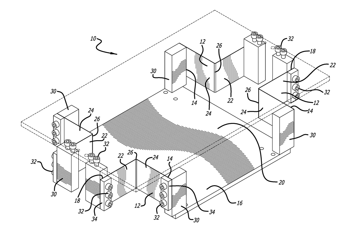
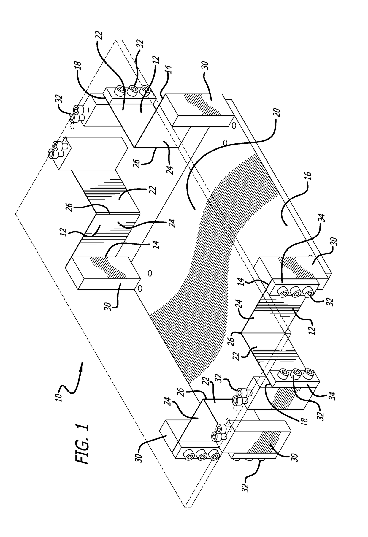
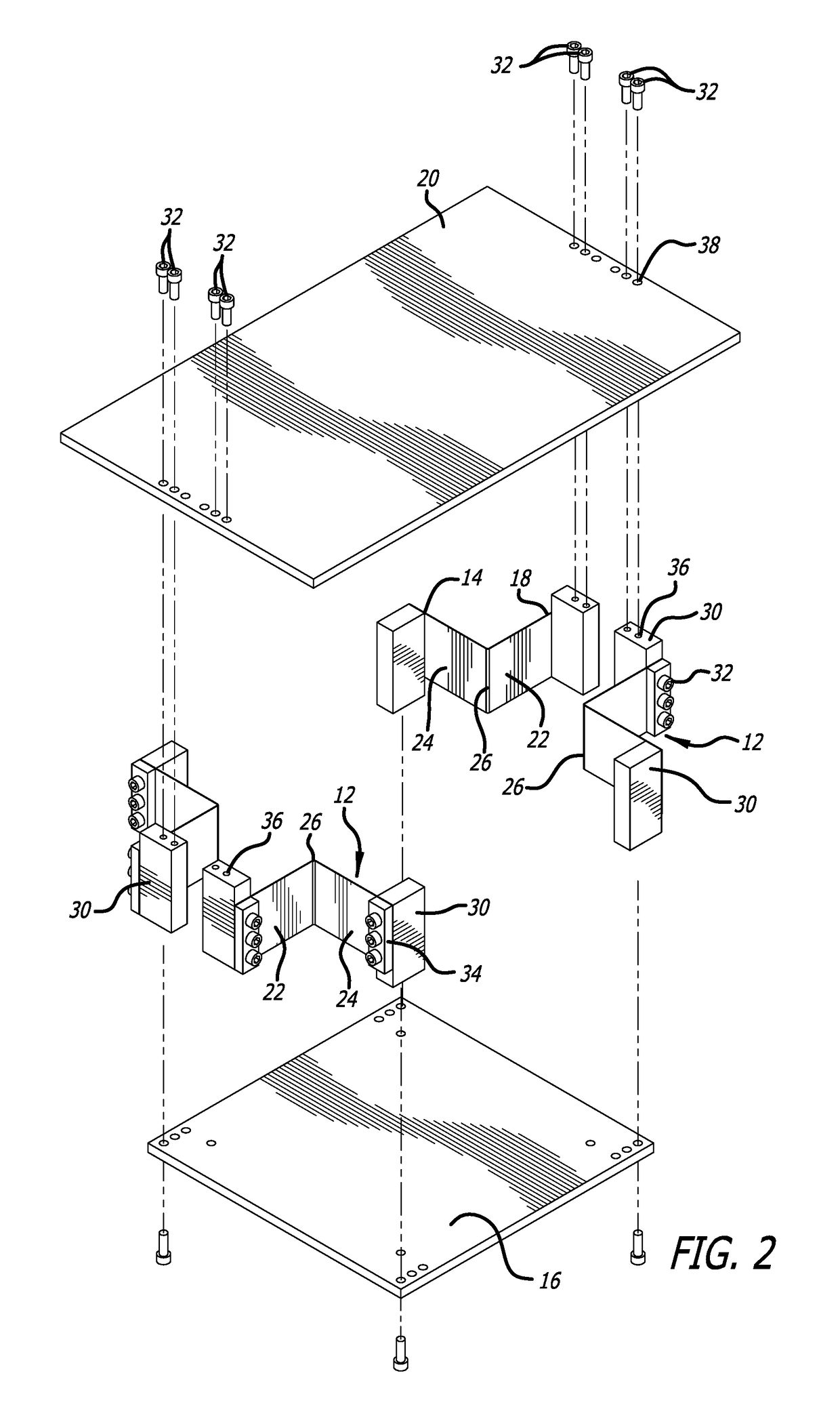
[0042]FIGS. 1-5 show one embodiment of a compact horizontal-motion isolator 10 made in accordance with the present invention. The embodiment of the horizontal-motion isolator 10 of FIGS. 1-5 is designed to support a payload (not shown) relative to a foundation (base) to reduce the transmission of horizontal vibrations (motion) between the payload and foundation.

[0043]The compact horizontal-motion isolator 10 of the present invention includes four support members in the form of bent flexures 12 that cooperatively support the object to be isolated from horizontal vibrations. Each of the bent flexures 12 have a first fixed or stationary end 14 coupled to a base platform 16 and a free or floating end 18 coupled to a top mounting plate 20 (shown in dashed lines in FIG. 1) that can be used in this particular embodiment for supporting the object to be isolated. The base platform 16 can sit on a foundation and may include leveling screws (not shown) used for leveling the base platform 16 re...


PUM


Abstract

A horizontal-motion vibration isolator utilizes a plurality of bent flexures to support an object to be isolated from horizontal motion. Each bent flexure includes a fixed end coupled to a base and a floating end which is cantilevered and coupled to the object being isolated. The arrangement of bent flexures allows the vertical height of the isolator to be reduced without compromising vibration isolation performance. Compressed springs or spring-like elements can be added to bear some of the weight of the object being isolated thus increasing the payload capacity of the isolator.

Description

BACKGROUND OF THE INVENTION[0001]The present invention relates generally to suspension systems for isolating and reducing the transmission of vibratory motion between an object or payload and a base and, more particularly, to a compact horizontal-motion vibration isolator and system which can be made lower in vertical height while at the same time making it less sensitive to changes in weight to effectively reduce the transmission of horizontal vibrations between the object and the base. An isolator made in accordance with the present invention provides low frequency isolation and provides high levels of vibration isolation performance while offering a physical form factor that is easy to integrate into instrumentation setups.[0002]The problems caused by unwanted vibration on equipment, devices and processes that are extremely motion sensitive have been widely researched and numerous solutions to prevent or reduce the transmission of vibratory motion have been proposed and developed...

Claims


Application Information

Patent Timeline
Patent Type & Authority Applications(United States)
IPC IPC(8): F16F15/04F16M11/22
CPCF16F15/046F16F2232/08F16M11/22F16F15/073F16F2236/027
Inventor RUNGE, ERIK
Owner MINUS K TECH
Why Eureka
Try Eureka