Touch panel apparatus

a technology of touch panel and control panel, which is applied in the direction of instruments, computing, electric digital data processing, etc., can solve the problems of incorrect operation, difficulty in adjusting the drive frequency of the touch panel to address, and inability to adjust the drive frequency of the touch panel, etc., and achieve the effect of suppressing an incorrect operation

Active Publication Date: 2018-04-26
TRIVALE TECH
View PDF3 Cites 3 Cited by
  • Summary
  • Abstract
  • Description
  • Claims
  • Application Information

AI Technical Summary

Benefits of technology

[0008]It is an object of the present invention to provide a touch panel apparatus which can be normally operated even during a dynamic change of a drive frequency of a touch panel for preventing interference with a disturbance noise, and can suppress an incorrect operation even in a case where a frequency of the disturbance noise fluctuates.
[0013]Even when some of the drive pulses interferes with the disturbance noise or the frequency of the disturbance noise fluctuates, the touch panel apparatus according to the present invention detects the coordinate using an electrostatic capacitance value measured by a drive pulse having the frequency which does not interfere with the disturbance noise, thus an incorrect operation due to the disturbance noise can be constantly suppressed, and the touch panel apparatus can be normally operated even during the change of the frequency of the drive pulse.

Problems solved by technology

The touch panel receives a disturbance noise caused by an inverter or switching power supply of a fluorescent light, and an incorrect operation such as a variation in a touch coordinate thereby occurs in some cases.
Such an incorrect operation occurs when a frequency of the disturbance noise and a drive frequency of the touch panel interfere with each other, however, the frequency of the disturbance noise is often unknown, so that it is difficult to adjust the drive frequency of the touch panel to address the incorrect operation in advance.
However, the method of Japanese Patent Application Laid-Open No. 2015-056151 has a problem that the incorrect operation may occur under the influence of the disturbance noise until the change of the drive frequency of the touch panel is completed.
The method of Japanese Patent Application Laid-Open No. 2015-056151 also has a problem that when the frequency of the disturbance noise fluctuates, the drive frequency which is dynamically changed and the frequency of the fluctuated disturbance noise interfere with each other, thereby causing the incorrect operation.
However, there is a problem that the former method performs the averaging procedure including the electrostatic capacitance value using the drive pulse interfering with the disturbance noise, thus it is difficult to completely exclude the influence of the disturbance noise, and the latter method performs the scan several times until the coordinate is determined, thus when a total number of indication bodies increases halfway through the procedure, the disturbance noise is hardly distinguished.

Method used


Image

  • Touch panel apparatus
  • Touch panel apparatus
  • Touch panel apparatus

Examples


embodiment 1

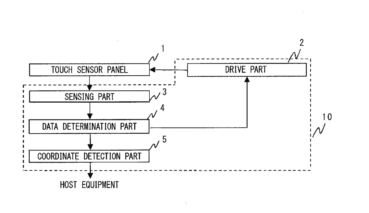
[0020]FIG. 1 is a schematic configuration diagram of a touch panel apparatus according to the embodiment 1 of the present invention. The touch panel apparatus illustrated in FIG. 1 includes a touch sensor panel 1 made up of (including) a plurality of sensors, a drive part 2 connected to the touch sensor panel 1 to output a plurality of drive pulses having different frequencies for measuring a capacitance, a sensing part 3 connected to a sensor constituting the touch sensor panel 1 to measure the capacitance for each of the plurality of drive pulses being output from the drive part 2, a data determination part 4 determining whether a measurement result of the capacitance for each of the plurality of drive pulses measured by the sensing part 3 is normal or abnormal, and a coordinate detection part 5 outputting a touch coordinate position of a touch performed by an indication body 11 in accordance with the measurement result of the capacitance which is determined to be normal by the da...

modification example 1

[0052]In the above embodiment 1, the data determination part 4 determines whether the electrostatic capacitance value is normal or abnormal using the average value of the electrostatic capacitance values measured by the sensing part 3, however, any method is applicable as long as it can determine the variation of the electrostatic capacitance value due to the disturbance noise, thus a median value obtained by arranging the measurement values in order and adopting a medium value, for example, may also be used. In the above case, when the variation in the plurality of electrostatic capacitance values occurs due to the interference with the disturbance noise, there is a probability that it can be determined whether the electrostatic capacitance value is normal or abnormal more accurately than the method of obtaining the average value including the abnormal value influenced by the noise.

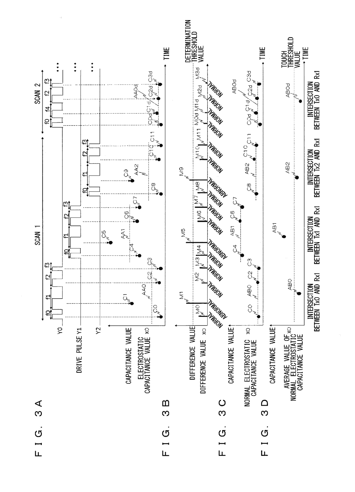
[0053]For example, in FIG. 3A, when the electrostatic capacitance values C0 to C3 obtained correspond...

modification example 2

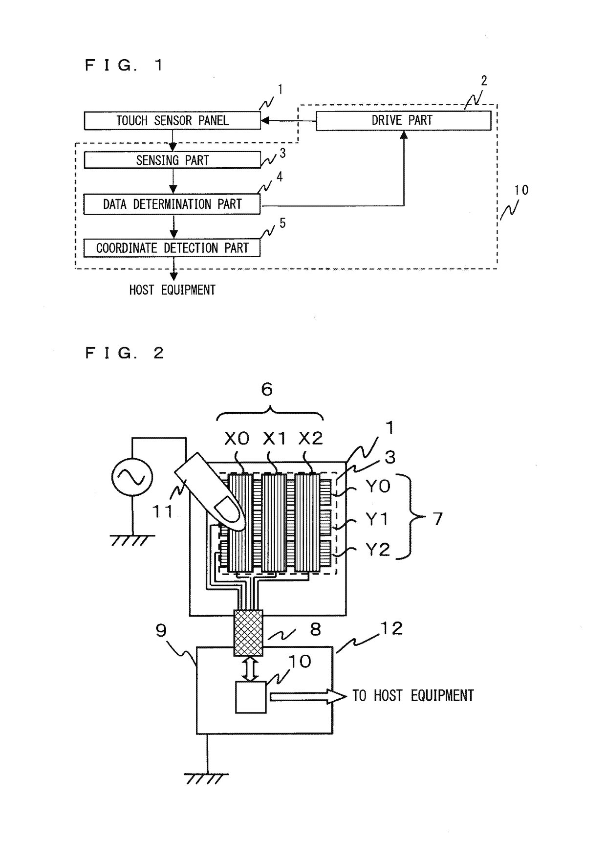
[0056]The measurement value may be corrected in accordance with the frequency to enhance the accuracy of the normal data determination and the coordinate detection in the capacitance measurement. For example, when a signal in which the drive pulse being output to the sensors Y0 to Y2 is excited in the sensors X0 to X2 via the capacitance of each intersection part is amplified by an amplifier, which has a frequency characteristic, to measure each electrostatic capacitance value, the electrostatic capacitance value may be corrected so as to compensate for the frequency characteristic of the amplifier in accordance with the frequencies f0 to f4 of the drive pulse being output to the sensors Y0 to Y2.


PUM


Abstract

A touch panel apparatus includes: a data determination part determining whether a measurement value of a capacitance for each of a plurality of drive pulses measured by a sensing part is normal or abnormal; and a coordinate detection part outputting a touch coordinate position of a touch performed by an indication body in accordance with the measurement value of the capacitance which is determined to be normal by the data determination part, wherein the drive part changes a frequency of a drive pulse in the plurality of drive pulses corresponding to the measurement value of the capacitance which is determined to be abnormal by the data determination part, and outputs, in a subsequent scan, a plurality of drive pulses including a drive pulse whose frequency has been changed.

Description

BACKGROUND OF THE INVENTIONField of the Invention[0001]The present invention relates to a touch panel apparatus, and can be preferably used in an information processing device with a touch input function using a touch panel.Description of the Background Art[0002]A touch panel which detects a touch performed by an indication body such as a finger to specify its position coordinate is mounted on a display apparatus, thereby attracting attention as one of remarkable user interface means as an alternative to a mechanical keyboard or mouse of the information processing device, and a touch panel in various forms such as a resistance film type or a capacitance type is commercialized.[0003]These various forms includes, as one of the capacitance types, a projected capacitive touchscreen type (referred to as the PCT type hereinafter) which enables a detection of the touch performed by the indication body even when a front surface side of a touch sensor panel having a plurality of built-in sen...

Claims


Application Information

Patent Timeline
Patent Type & Authority Applications(United States)
IPC IPC(8): G06F3/041G06F3/044
CPCG06F3/0418G06F3/044G06F2203/04111G06F3/04166G06F3/0446
Inventor SHIMASAKI, YUSUKEMORI, SEIICHIRO
Owner TRIVALE TECH
Why Eureka
Try Eureka