
Powered lower limb devices and methods of control thereof

a technology of lower limbs and robotic devices, which is applied in the field of powered prosthetics and orthotics, and bipedal robotic devices, can solve the problems that current commercially available exoskeletons fail to accurately replicate the human walk

Active Publication Date: 2018-05-03
UNIVERSITY OF NEW BRUNSWICK
View PDF0 Cites 33 Cited by
  • Summary
  • Abstract
  • Description
  • Claims
  • Application Information

AI Technical Summary

Benefits of technology

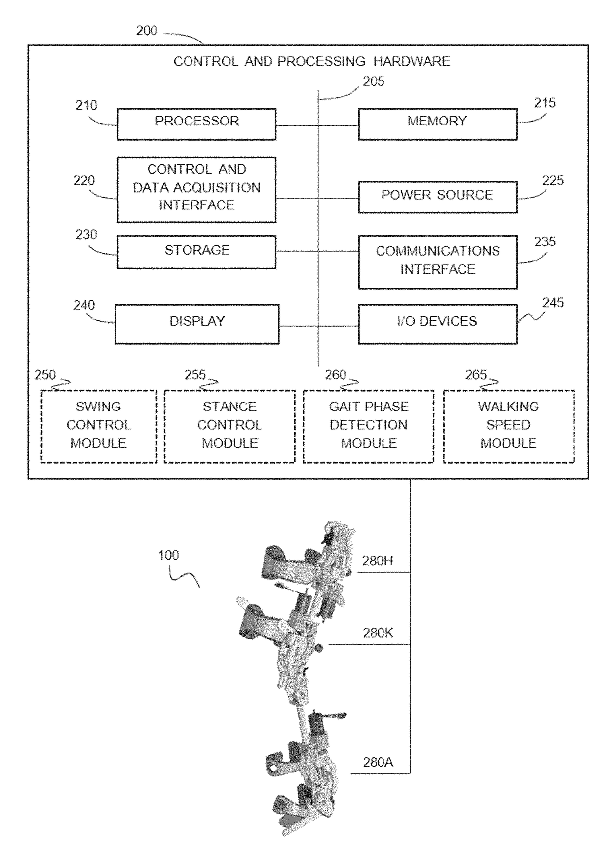
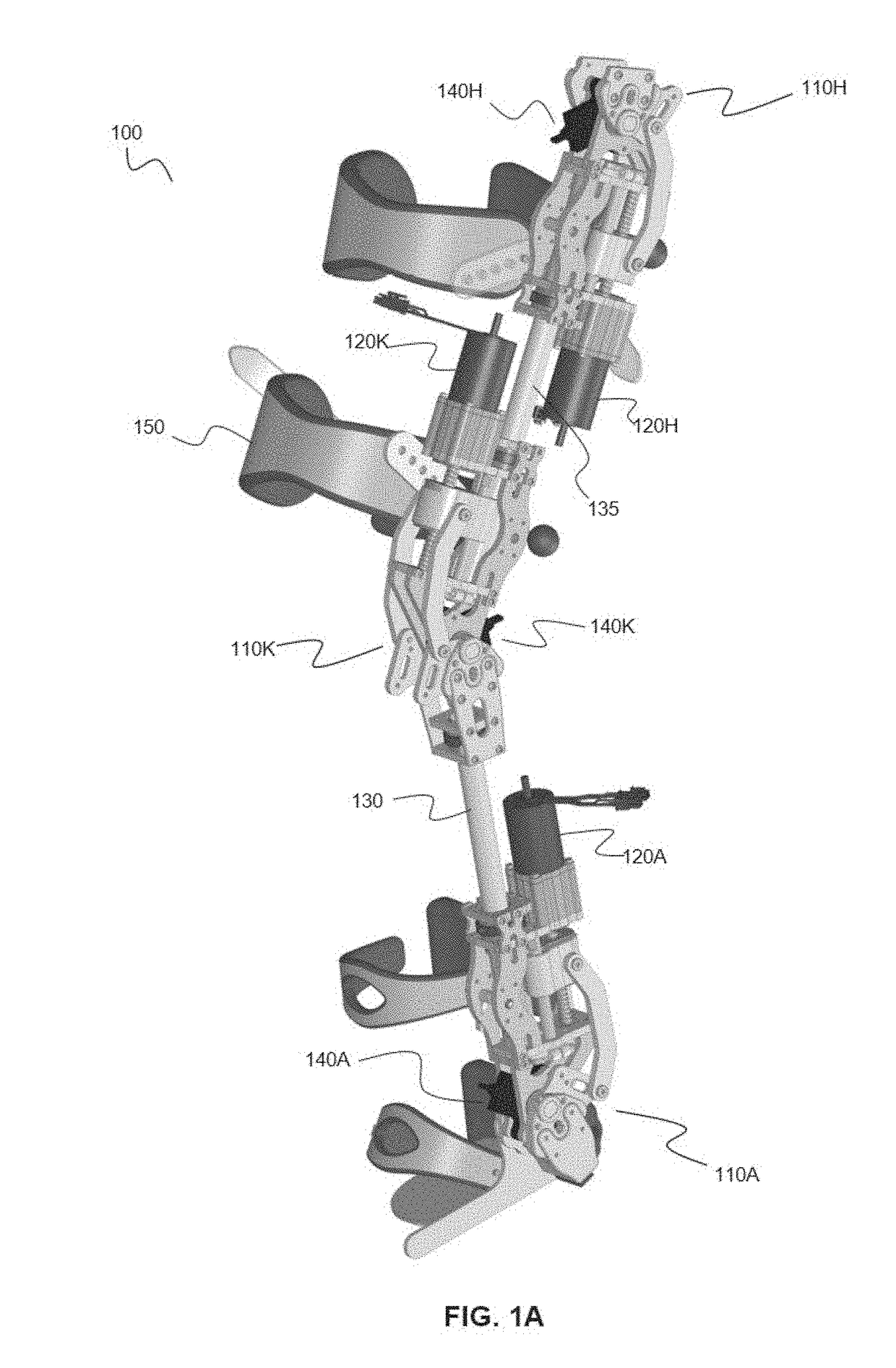
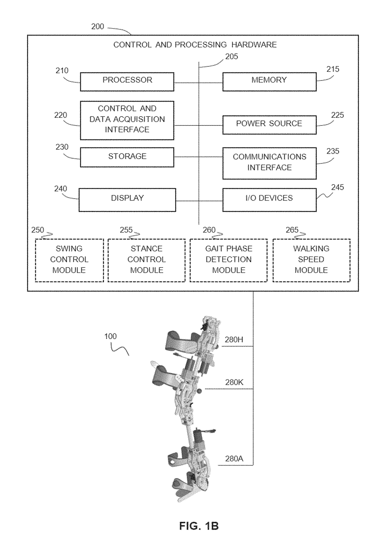
The patent text describes methods and devices for controlling a powered lower limb device, such as a prosthesis or orthosis, during the stance phase of a walking cycle. The methods involve using angle sensors and inertial sensors to determine the joint angles and the speed of the device. The device can then be controlled to provide a pre-determined torque at the hip joint, knee joint, or ankle joint, based on the difference between the joint angles and the walking speed. The joint assembly includes a support frame, a motor, a screw, and a crank, which can be customized for different anatomical joints. The technical effects of the patent text include improved control and customization of the powered lower limb device for better performance and comfort during the stance phase of a walking cycle.

Problems solved by technology

Current commercially available exoskeletons fail to accurately replicate the human walk due to their non-powered ankle design or inadequate control scheme.

Method used


Image

  • Powered lower limb devices and methods of control thereof
  • Powered lower limb devices and methods of control thereof
  • Powered lower limb devices and methods of control thereof

Examples


Embodiment Construction

[0067]Various embodiments and aspects of the disclosure will be described with reference to details discussed below. The following description and drawings are illustrative of the disclosure and are not to be construed as limiting the disclosure. Numerous specific details are described to provide a thorough understanding of various embodiments of the present disclosure. However, in certain instances, well-known or conventional details are not described in order to provide a concise discussion of embodiments of the present disclosure.

[0068]As used herein, the terms “comprises” and “comprising” are to be construed as being inclusive and open ended, and not exclusive. Specifically, when used in the specification and claims, the terms “comprises” and “comprising” and variations thereof mean the specified features, steps or components are included. These terms are not to be interpreted to exclude the presence of other features, steps or components.

[0069]As used herein, the term “exemplar...


PUM


Abstract

In some aspects, methods are provided for controlling a powered lower limb device. A stance phase control method is disclosed in which the required joint torque is determined based on the difference between two joint angles, such as the knee joint and the ankle joint. A swing control method is also disclosed that employs feedback-based minimum jerk trajectory control. In other embodiments, a joint assembly for use in modular lower limb device is provided. The joint assembly includes a reconfigurable slider-crank mechanism that is configurable to provide a plurality of different ranges of rotational travel, rotational speeds, and torques, for customization according to different anatomical joints. The joint assembly may include a compact coupling device for coupling a ball screw of the slider-crank mechanism to an output shaft of a motor. When employed to form a modular orthosis, the joint assembly may be adapted for self-alignment as its length adjustment method during setup.

Description

CROSS-REFERENCE TO RELATED APPLICATION[0001]This application claims priority to U.S. Provisional Application No. 62 / 417,192, titled “POWERED LOWER LIMB DEVICES AND METHODS OF CONTROL THEREOF” and filed on Nov. 3, 2016, the entire contents of which is incorporated herein by reference.BACKGROUND[0002]The present disclosure relates to powered prosthetic and orthotic devices, and to bipedal robotic devices.[0003]Every year, more than 7800 people incur a spinal cord injury in North America. Although around 44% will end up with complete loss of locomotion, the fortunate ones can benefit from clinical rehabilitation to help recover motor control. Some therapy methods make use of a powered exoskeleton to support the impaired limbs, and guide them through the human walking cycle numerous times. Powered orthoses, such as powered exoskeletons, offer the promise of low-cost rehabilitation, together with empowering wheelchair bound individuals to walk, climb stairs, and stand again. Current comm...

Claims


Application Information

Patent Timeline
Patent Type & Authority Applications(United States)
IPC IPC(8): A61F2/68A61H3/00A61F5/01A61H1/02
CPCA61F2/68A61H3/00A61F5/0123A61H1/024A61H2201/5069A61H2201/1207A61F2002/7625B25J9/0006A61H2201/5061B25J9/106A61H2003/007A61H2201/1409A61H2201/1418A61H2201/1436A61H2201/5007A61H2205/10A61F2/70
Inventor QUINN, NATHANGRANDMAISON, CHRISTIANSENSINGER, JONATHON
Owner UNIVERSITY OF NEW BRUNSWICK
Learn More