Electronic brake system and control method thereof

a technology of electronic brakes and control methods, applied in the direction of braking systems, braking components, transportation and packaging, etc., can solve the problems of large error between an estimated braking pressure and an actual braking pressure of each wheel, and the electronic brake system

Active Publication Date: 2018-05-03
HL MANDO CORP
View PDF1 Cites 2 Cited by
  • Summary
  • Abstract
  • Description
  • Claims
  • Application Information

AI Technical Summary

Benefits of technology

[0013]The control unit may restart to control the motor and the valves on the basis of the hydraulic pressure information and the displacement information of the brake pedal after synchronizing a pressure of the wheel cylinder.
[0014]The control unit may detect that the at least one or more valves are opened or closed a predetermined number of times or more during a predetermined time period during an anti-lock brake system (ABS) or traction control system (TCS) control.
[0015]In accordance with another aspect of the present disclosure, a control method of an electronic brake system includes: controlling a hydraulic pressure delivered to wheel cylinders provided in wheels by opening or closing at least one or more valves; measuring the hydraulic pressure delivered to the wheel cylinders provided in the wheels; determining whether the at least one or more valves are detected as being opened or closed a predetermined number of times or more during a predetermined time period; opening at least one or more valves that deliver the hydraulic pressure to a corresponding wheel cylinder and closing at least one or more valves that deliver the hydraulic pressure to the remaining wheel cylinders other than the corresponding wheel cylinder when the at least one or more valves are detected as being opened or closed a predetermined number of times or more during a pre

Problems solved by technology

In this case, when a brake hydraulic pressure is controlled by an ABS for preventing wheels from locking up while braking, a BTCS for preventing drive wheels from slipping upon a sudden unintended acceleration or a sudden acceleration of a vehicle, and a combination of the ABS and transa

Method used


Image

  • Electronic brake system and control method thereof
  • Electronic brake system and control method thereof
  • Electronic brake system and control method thereof

Examples


Embodiment Construction

[0027]Hereinafter, embodiments of the present disclosure will be described in detail with reference to the accompanying drawings. The following embodiments are provided to fully convey the spirit of the disclosure to those skilled in the art. The present disclosure may, however, be embodied in different forms and should not be construed as limited to the embodiments set forth herein. In the drawings, some elements that need not be used to describe the present disclosure will be omitted for clarity, and some elements may be exaggerated to facilitate an understanding of the present disclosure.

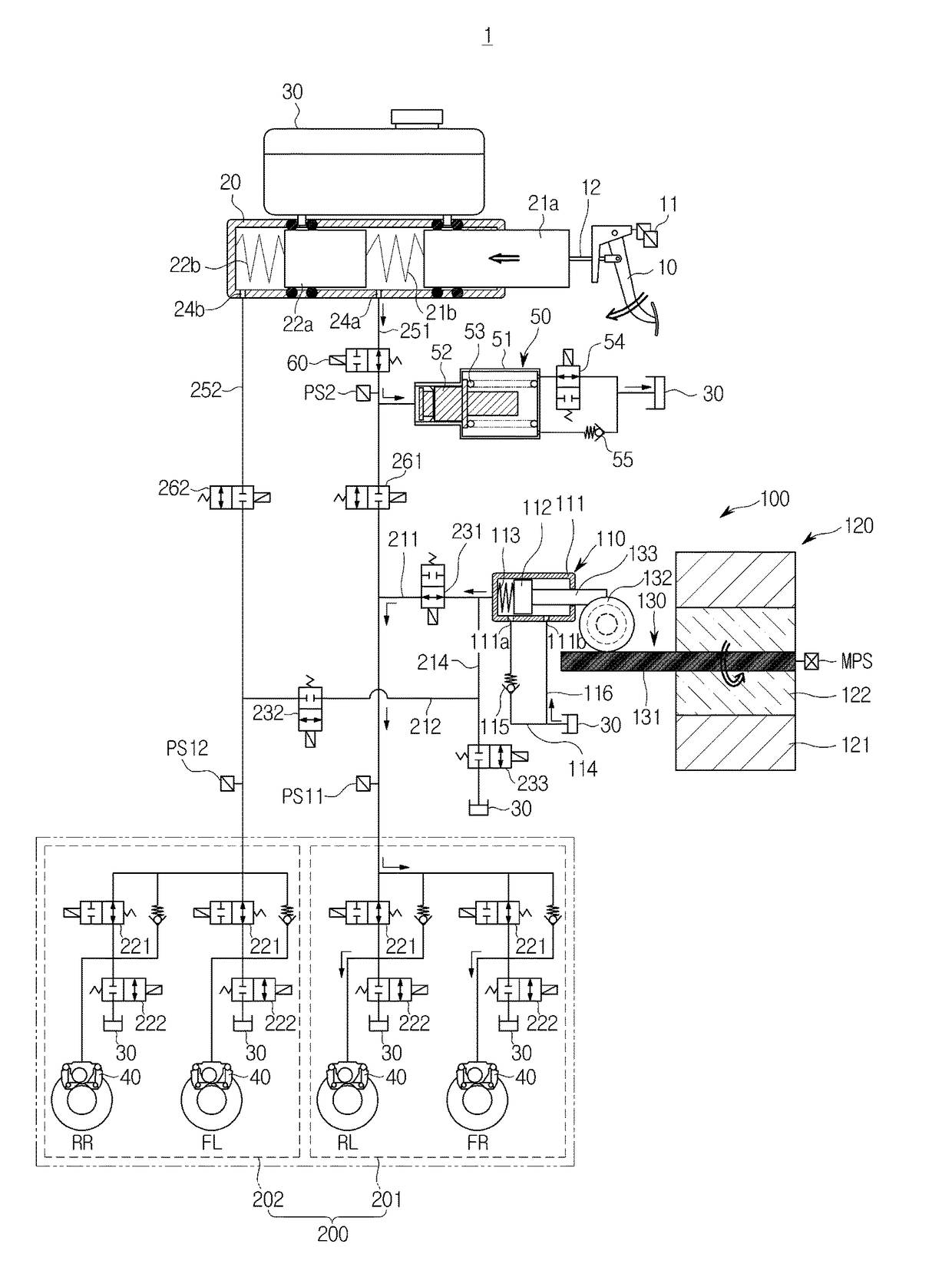
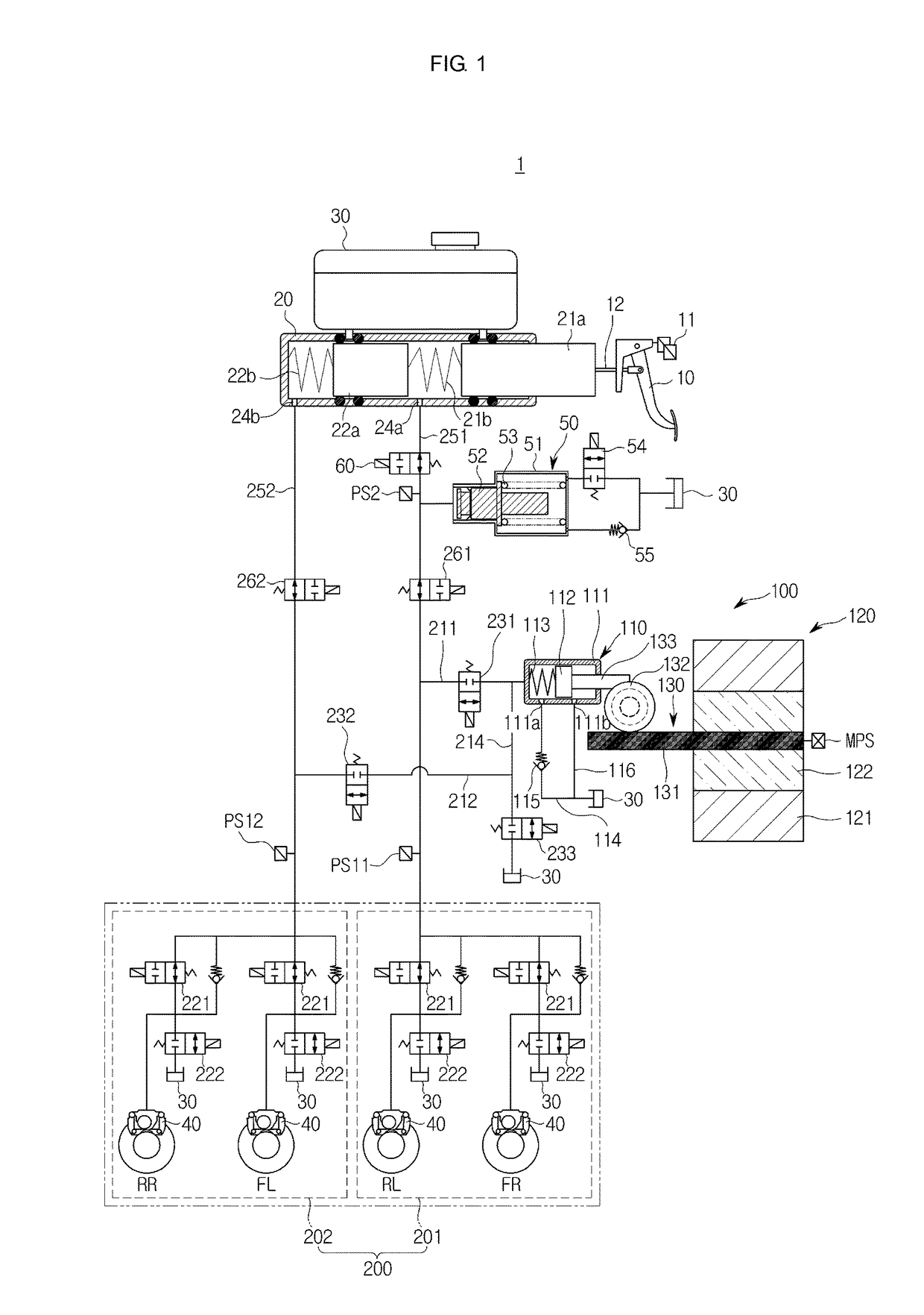
[0028]FIG. 1 is a hydraulic circuit diagram showing a non-braking state of an electronic brake system 1 according to an embodiment of the present disclosure.

[0029]Referring to FIG. 1, typically, the electronic brake system 1 includes a master cylinder 20 configured to generate a hydraulic pressure, a reservoir 30 connected to an upper portion of the master cylinder 20 and configured to store oil,...


PUM


Abstract

Disclosed herein is an electronic brake system, which includes at least one or more valves provided to control a hydraulic pressure delivered to wheel cylinders provided in wheels, a pressure measurer configured to measure the hydraulic pressure delivered to the wheel cylinders provided in the wheels, and a controller configured to open at least one or more valves that deliver the hydraulic pressure to a corresponding wheel cylinder and close at least one or more valves that deliver the hydraulic pressure to the remaining wheel cylinders other than the corresponding wheel cylinder when the at least one or more valves are detected as being opened or closed a predetermined number of times or more during a predetermined time period, and synchronize the measured hydraulic pressure with a hydraulic pressure of the wheel cylinder having all of the at least one or more valves open.

Description

CROSS-REFERENCE TO RELATED APPLICATION[0001]This application claims the benefit of Korean Patent Application No. 2016-0140697, filed on Oct. 27, 2016 in the Korean Intellectual Property Office, the disclosure of which is incorporated herein by reference.BACKGROUND1. Field[0002]Embodiments of the present disclosure relate to an electronic brake system, and more particularly, to a control method for minimizing an error between an actual brake pressure and an estimated brake pressure of each wheel in an electronic brake system configured to generate a braking force using an electric signal corresponding to a displacement of a brake pedal.2. Description of the Related Art[0003]A vehicle is necessarily equipped with a brake system for braking the vehicle. Lately, several kinds of systems for obtaining a strong and stable braking force are being proposed.[0004]Examples of brake systems include an anti-lock brake system (ABS) for preventing wheels from locking up while braking, a brake tra...

Claims


Application Information

Patent Timeline
IPC IPC(8): B60T8/40B60T7/04B60T8/175B60T8/1761B60T13/14
CPCB60T8/404B60T7/042B60T8/175B60T8/1761B60T13/142B60T2220/04B60T13/662B60T17/22B60T2270/406B60T8/176B60T17/226B60T8/5025B60T8/1701B60T8/171B60T2270/10B60T2270/88
Inventor KO, YEON-BEN
Owner HL MANDO CORP
Why Eureka
Try Eureka