Brake control apparatus and control method thereof

a technology of brake control apparatus and control method, which is applied in the direction of brake cylinders, vehicle components, braking systems, etc., can solve the problems of changing the capacity to which the working fluid is supplied, and achieve the effect of improving the controllability of performing

Active Publication Date: 2007-05-24
TOYOTA JIDOSHA KK
View PDF3 Cites 31 Cited by
  • Summary
  • Abstract
  • Description
  • Claims
  • Application Information

AI Technical Summary

Benefits of technology

[0007] The invention provides a brake control apparatus that improves the controllability in performing a con...

Problems solved by technology

However, the actuation of the retention valves changes the capaci...

Method used


Image

  • Brake control apparatus and control method thereof
  • Brake control apparatus and control method thereof
  • Brake control apparatus and control method thereof

Examples


first embodiment

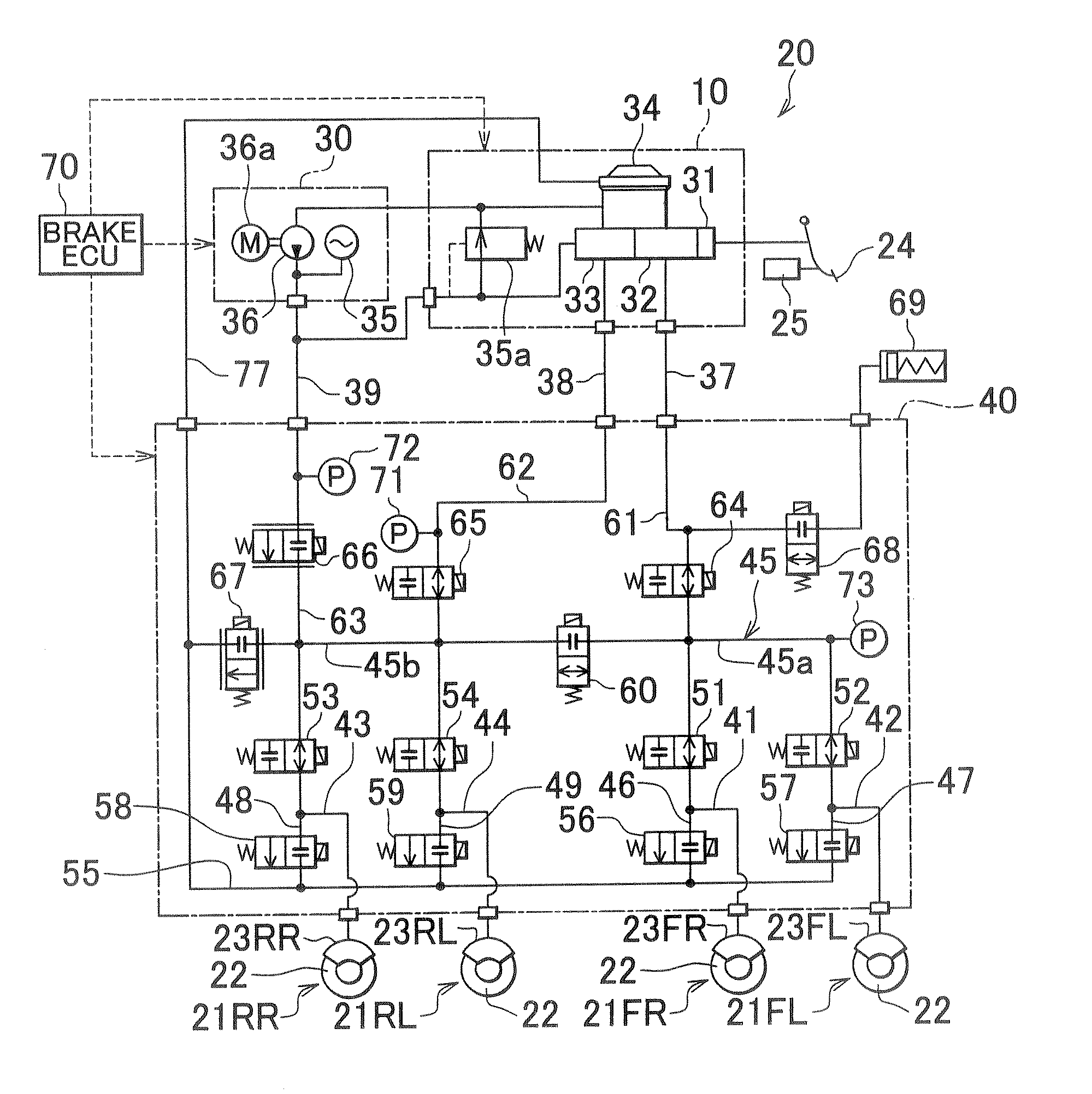
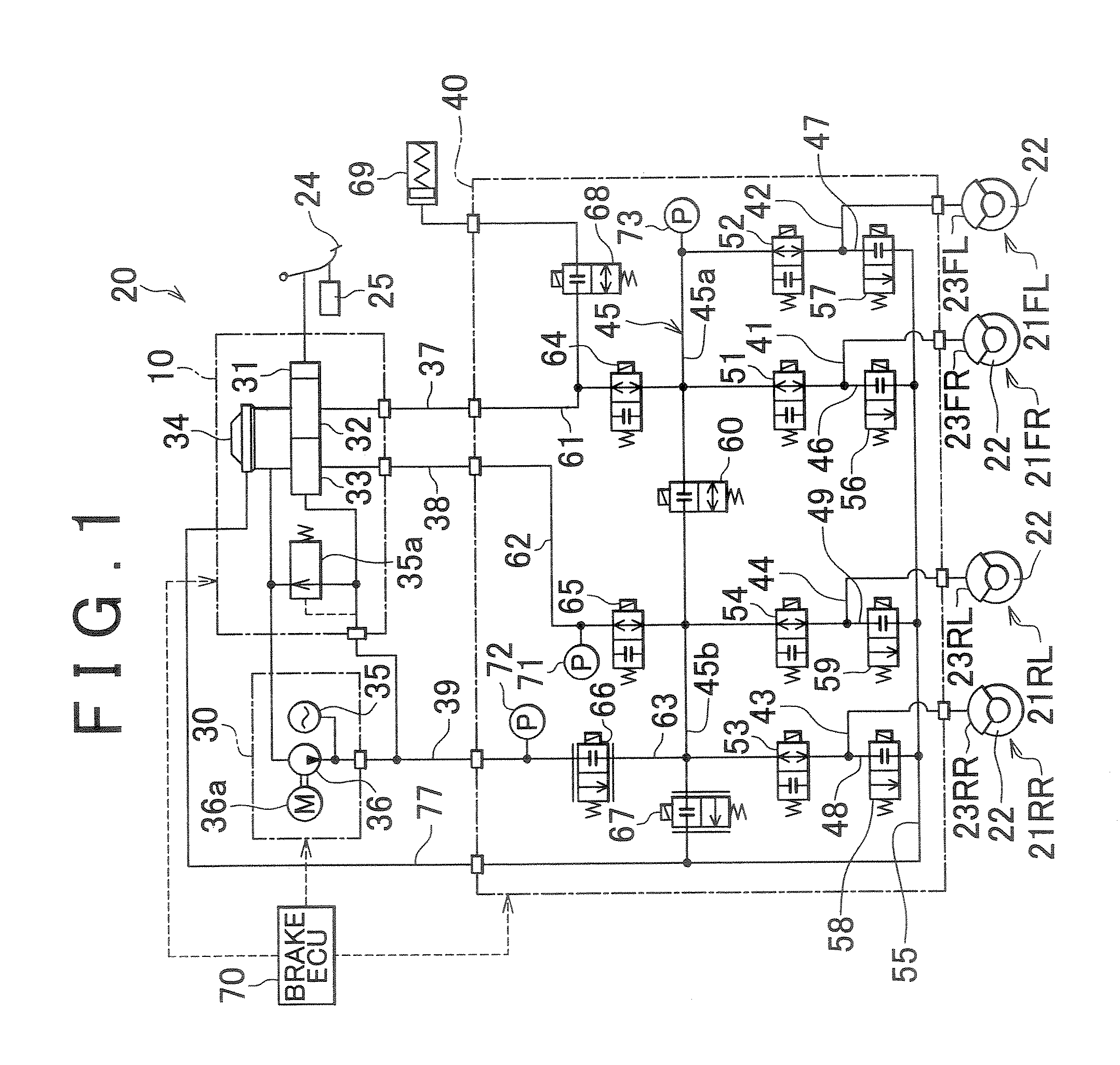
[0028]FIG. 1 is a system diagram showing a brake control apparatus 20 in accordance with the invention. The brake control apparatus 20 constitutes a vehicular electronic control brake system (ECB), and controls the braking forces applied to the four wheels provided on the vehicle. The brake control apparatus 20, in accordance with this embodiment, may be installed in, for example, a hybrid vehicle equipped with an electric motor and an internal combustion engine as power sources for driving the vehicles. In such a hybrid vehicle, there are two modes of braking the vehicle. In particular, a regenerative braking mode, in which the vehicle is braked by regenerating kinetic energy of the vehicle into electric energy, and a hydraulic pressure braking mode, which is carried out by the brake control apparatus 20, can be used for the braking of the vehicle. The vehicle in this embodiment can execute a brake regeneration cooperative control of generating desired braking force through the com...

second embodiment

[0089]FIG. 4 is a graph schematically showing examples of transitions of the hydraulic pressure and the control current in the FIG. 4 shows the control current and the control hydraulic pressure in the case where the feedforward control law is used as well.

[0090] In the upper portion of FIG. 4, fluctuations in the primary side hydraulic pressure (upstream pressure) of the ABS retention valves 51 to 54, and fluctuations in pressure in a specific wheel cylinder X and a specific wheel cylinder Y are shown by solid lines. The vertical axis represents the pressure, and the horizontal axis represents time. In the lower portion of FIG. 4, the sum of the control currents supplied to the pressure intensifying linear control valve 66, the FF control current computed by the feedforward control law, and the FB control current computed by the feedback control law are shown sequentially from above. The pressure intensifying linear control valve 66 is controlled through the supply of the control ...


PUM


Abstract

The invention provides a brake control apparatus that improves the controllability of a vehicle in the control for restraining slip of the wheels. The brake control apparatus includes: wheel cylinders that apply braking force individually to wheels by supplying a working fluid; retention valves that are provided respectively upstream of the wheel cylinders and that are opened and closed so as to restrain slip of the wheels; a common control valve provided upstream of the retention valves to supply the working fluid to the wheel cylinders; and a control portion that controls the common control valve by different control laws to restrain fluctuations in pressure on a primary side of the retention valves caused by fluctuations in a capacity to which the working fluid from the common control valve is supplied, by opening or closing of the retention valves.

Description

INCORPORATION BY REFERENCE [0001] The disclosure of Japanese Patent Application No. 2005-334537 filed on Nov. 18, 2005 including the specification, drawings and abstract is incorporated herein by reference in its entirety. BACKGROUND OF THE INVENTION [0002] 1. Field of the Invention [0003] The invention relates to a brake control apparatus that controls the braking force applied to a wheel provided in a vehicle, and a control method thereof. [0004] 2. Description of the Related Art [0005] An antiskid brake apparatus in which the control gain at a pressure intensifying stage of a control cycle accomplished by an antiskid control means for controlling the slip rate of wheels is changed in accordance with the magnitude of brake hydraulic pressure that is generated corresponding to the brake pedal operation is described in Japanese Patent Application Publication No. JP-A-05-301567. In the described antiskid brake apparatus, the pressure intensifying control gain changes in accordance wi...

Claims


Application Information

Patent Timeline
IPC IPC(8): B60T8/42
CPCB60T8/17616B60T8/36B60T8/4081
Inventor OHKUBO, MASAYASUMIZUTANI, YASUJISAKAZAKI, KAZUYOSHI
Owner TOYOTA JIDOSHA KK
Why Eureka
Try Eureka