Brake control apparatus

Inactive Publication Date: 2013-03-14
HITACHI AUTOMOTIVE SYST LTD
View PDF0 Cites 31 Cited by
  • Summary
  • Abstract
  • Description
  • Claims
  • Application Information

AI Technical Summary

Benefits of technology

[0004]It is an object of the present invention to provide a brake control apparatus which is d

Problems solved by technology

However, in the conventional brake control apparatus, it is, therefore, difficult to arbitrarily control the wheel cyli

Method used


Image

  • Brake control apparatus
  • Brake control apparatus
  • Brake control apparatus

Examples


first embodiment

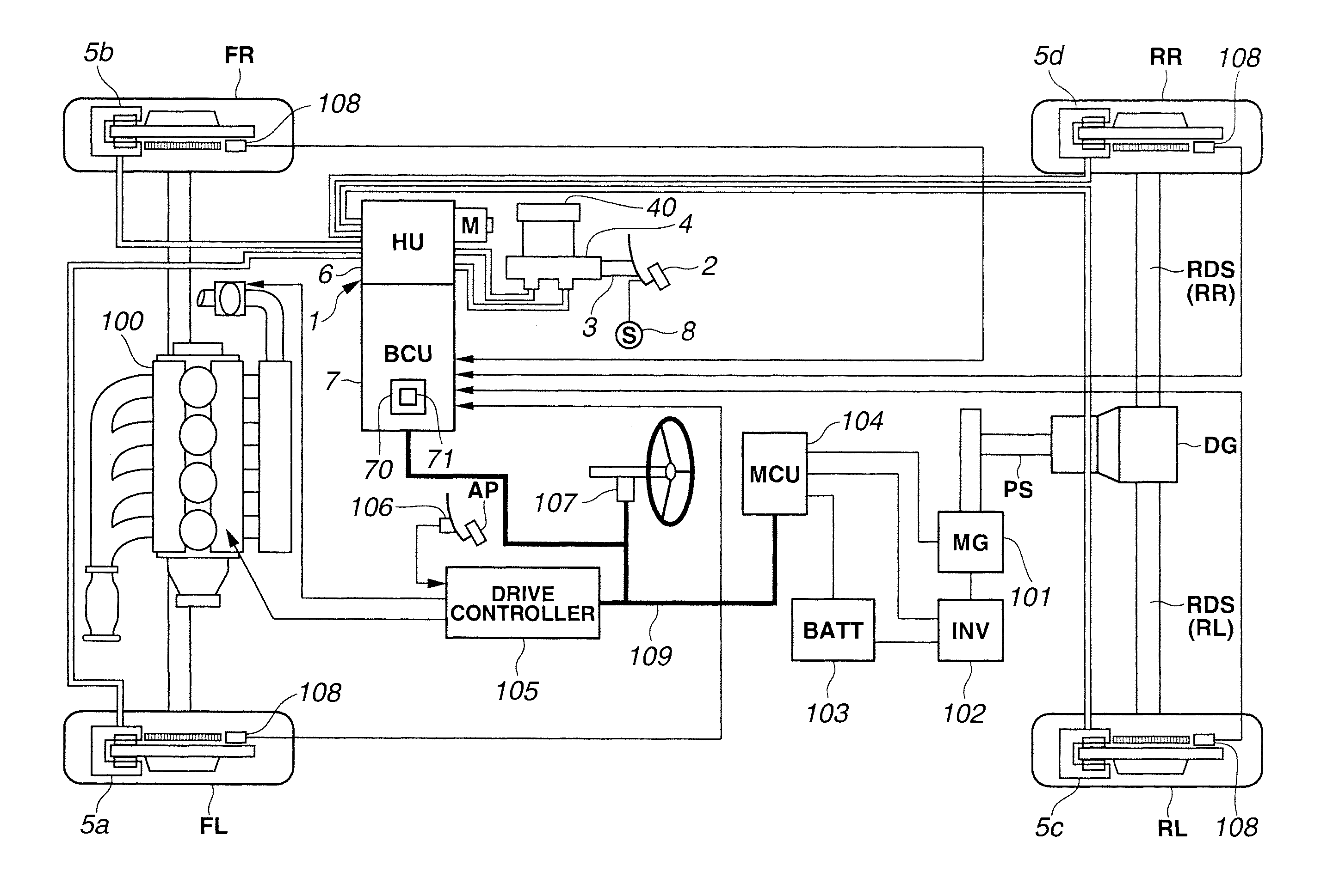
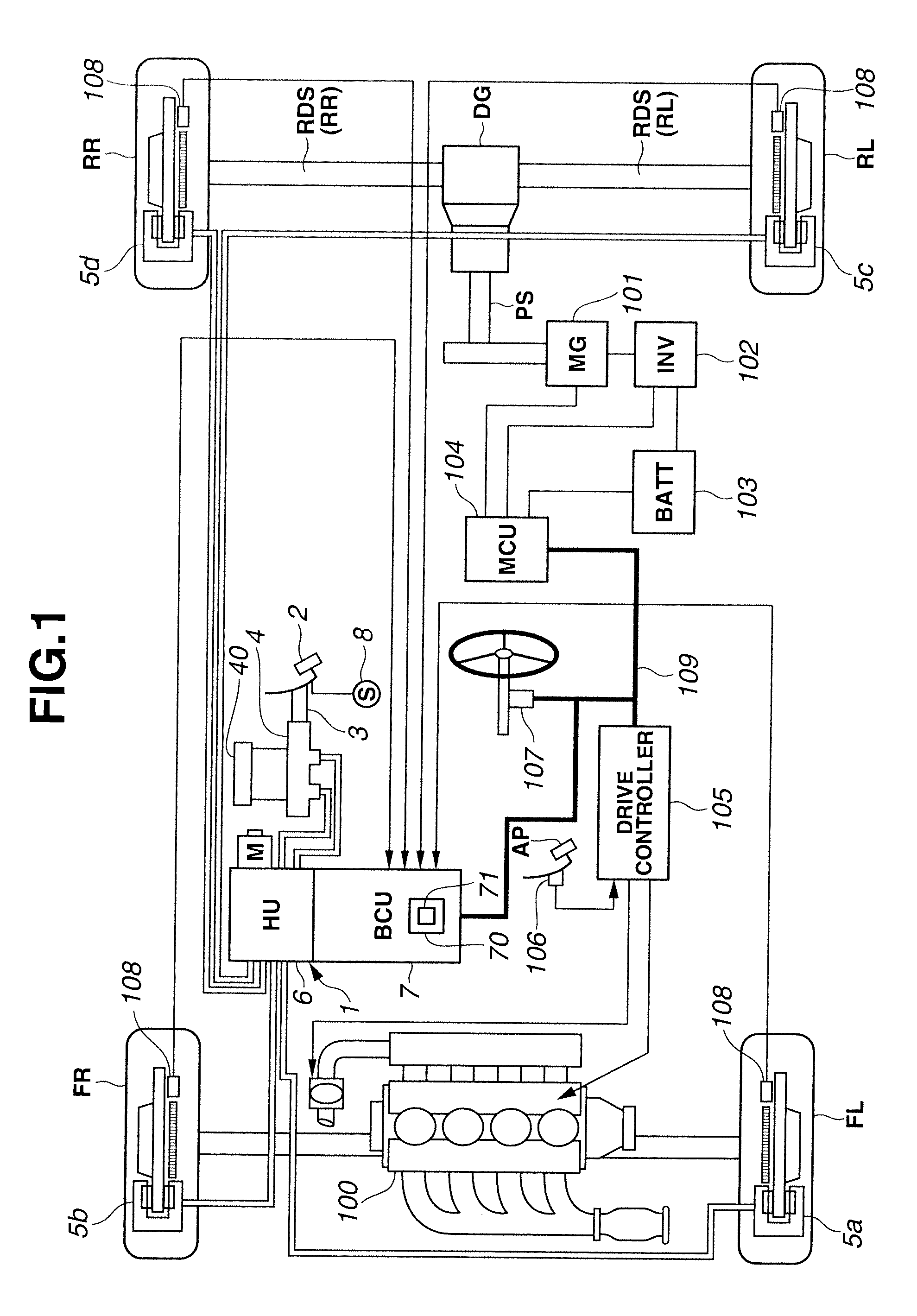
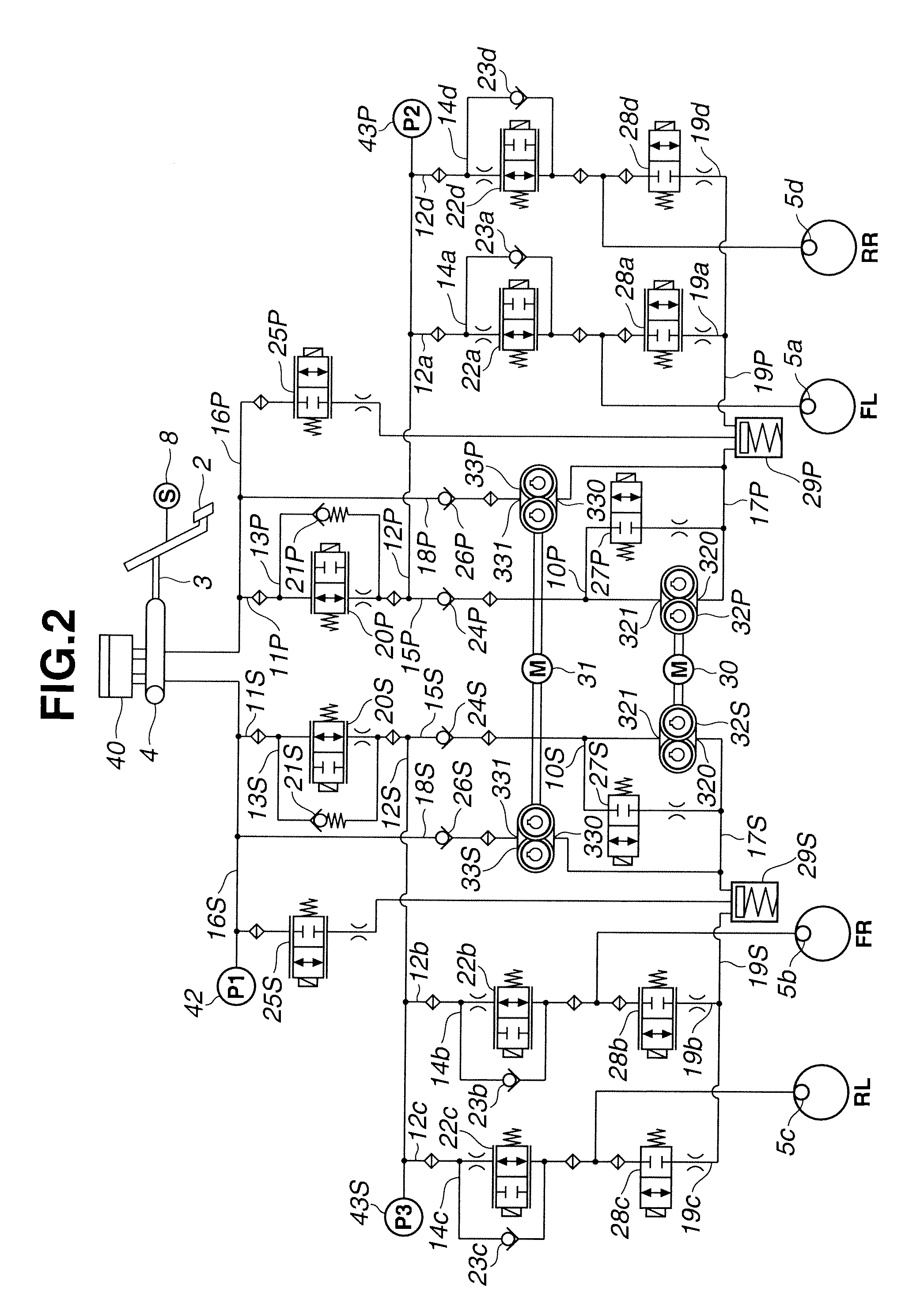
[0054]FIG. 1 is a view showing a system configuration of a driving system and a braking system of a vehicle to which a brake control apparatus 1 according to a first embodiment of the present invention is applied. FIG. 2 is a view showing a circuit configuration of the brake control apparatus 1 according to the first embodiment of the present invention. The vehicle is a hybrid vehicle including front wheels FL and FR driven by an internal combustion engine (engine 100), and rear wheels RL and RR driven by an electric motor (motor generator 101). Wheels FL, FR, RL, and RR are provided, respectively, with wheel speed sensing sections (wheel speed sensors) 108 arranged to sense respective rotational speeds (wheel speeds). Electronic control units (a control unit 7, a motor control unit 104, and a drive controller 105) are connected with each other by signal wires (CAN communication lines 109) capable of exchanging information with each other. A driving system of the vehicle includes en...

second embodiment

[0166]In a brake control apparatus according to a second embodiment of the present invention, gate-in valve 25, recirculating device (second pump 33), and the recirculating circuit (pipe 18) are provided only to one of the two systems (the P system and the S system) of the piping structures of hydraulic pressure control unit 6, for example, only to the S system, unlike the brake control apparatus according to the first embodiment.

[0167]First, a structure of the brake control apparatus according to the second embodiment is illustrated. FIG. 44 is a circuit diagram showing a hydraulic pressure control apparatus according to the second embodiment. A structure of the S system is identical to that of the brake control apparatus according to the first embodiment. Pipe 18 and second pump 33 are not provided in the P-system. Second motor 31 drives only second pump 33S of the S-system. Gate-in valve 25 is not provided on the third brake circuit (pipe 16) of the P-system. Reservoir 29P of the...

third embodiment

[0172]In a brake control apparatus 1 according to a third embodiment of the present invention, second pump 33 is not provided on the recirculating circuit (pipe 18), as the recirculating device in the hydraulic pressure control unit 6. Alternatively, first pump 32 is arranged to actuate as the recirculating device, unlike the brake control apparatus according to the first embodiment.

[0173]FIG. 45 is a circuit diagram of hydraulic pressure control unit 6 of brake control apparatus 1 according to the third embodiment. Pipe 18 and second pump 33 are not provided in the P system and the S system, unlike FIG. 2. Second switching valves 41P and 41S which are normally-open solenoid valves are provided on portions of pipes 12P and 12S which are forward (upstream) of bifurcating points at which pipes 12P and 12S are bifurcated into pipes 12a, 12d, 12b, and 12c of the respective wheels. A hydraulic pressure sensor 44 is provided on the connection point between pipe 11 and pipe 12, and arrange...


PUM


Abstract

A brake control apparatus for a vehicle provided with a regenerative braking device, the brake control apparatus includes: a first brake circuit connecting a master cylinder configured to generate a brake hydraulic pressure by a brake operation of a driver, and a wheel cylinder to which the brake hydraulic pressure is applied; a booster configured to increase a pressure of a brake fluid within the master cylinder, and to transmit the pressurized brake fluid to the wheel cylinder through a second brake circuit connected with the first brake circuit; a third brake circuit bifurcated from the first brake circuit, and connected with the booster; a reservoir provided on the third brake circuit; and a recirculating device configured to recirculate the brake fluid stored in the reservoir, to the first brake circuit's side.

Description

BACKGROUND OF THE INVENTION[0001]This invention relates to a brake control apparatus.[0002]Japanese Patent Application Publication No. 2002-67907 discloses a conventional brake control apparatus for a vehicle provided with a regenerative braking device, which is configured to generate a frictional braking force so as to compensate for deficiency of a regenerative braking force with respect to a driver's requested (desired) braking force, that is, to perform a regenerative coordinated control. This brake control apparatus performs a hydraulic pressure control for generating the frictional braking force. This brake control apparatus includes a first brake circuit connecting a master cylinder and a wheel cylinder, a booster configured to increase the pressure of the brake fluid (hydraulic fluid) within the master cylinder, and to transmit the pressurized brake fluid to the wheel cylinder through a second brake circuit connected with the first brake circuit, a third brake circuit bifurc...

Claims


Application Information

Patent Timeline
IPC IPC(8): B60T13/58
CPCB60T2270/604Y02T10/70B60T8/442B60T8/4872B60T1/10B60T13/586B60W10/08B60W10/188B60W30/18127B60K2001/001B60W2510/182B60Y2300/89Y02T10/7077Y02T10/7044Y02T10/7005Y02T10/705Y02T10/642B60L7/26B60L7/14B60L11/14B60L11/1861B60L15/2009B60L2220/14B60L2240/12B60L2240/421B60L2260/28Y02T10/7275B60T8/4054Y02T10/72B60L50/16B60L58/15Y02T10/64Y02T10/7072F16D61/00
Inventor YAGASHIRA, HIDEAKI
Owner HITACHI AUTOMOTIVE SYST LTD
Why Eureka
Try Eureka