Fairing for an aircraft

a technology for aircraft and fairing, applied in the direction of engine seals, aircraft stabilisation, engine components, etc., can solve the problems of heavy overall design, complex design and manufacturing, complex and expensive design and manufacturing, etc., to prevent contaminant ingress transitioning, improve structural arrangement, and reduce friction

Active Publication Date: 2018-05-03
AIRBUS OPERATIONS GMBH
View PDF6 Cites 0 Cited by
  • Summary
  • Abstract
  • Description
  • Claims
  • Application Information

AI Technical Summary

Benefits of technology

[0016]Having an interface further provided with at least one seal formed using a ply of resilient material may be preferable when a seal design that is less prone to edge erosion is required. Furthermore, such an arrangement may also provide an interface where less deformation of the seal occurs during operation, which will result in an even smoother aerodynamic surface between the first and second fairing portions.
[0017]In a further embodiment, the fairing may comprise an interface that is an overlapping type of interface defined by overlapping corresponding edges of the first fairing portion and second fairing portion when they are fixedly attached to the first structural component and second structural component, respectively. Such an interface may provide an improved structural arrangement such that aerodynamic pressure loads acting normal to the surface of the fairing may be distributed more evenly between the first and second portions of the fairing, while still ensuring that induced loads due to relative movement between the first and second structural components are minimized or avoided entirely.
[0018]In another embodiment, the interface that is defined by overlapping corresponding edges further comprises at least one seal, configured to further prevent contaminant ingress transitioning through the interface.
[0019]Such an interface may, in addition or alternatively, be provided with a friction reducing coating and / or part configured to reduce friction between the edge of the first fairing portion and the corresponding edge of the second fairing portion when the aerodynamic fairing is in use. This may reduce mechanical wear of the fairing during its service life, therefore reducing the need for removal of the fairing from the aircraft for maintenance or repair.

Problems solved by technology

Ultimately, this leads to a conservative design that overall is heavy, as well as complex and expensive to design and manufacture.

Method used


Image

  • Fairing for an aircraft
  • Fairing for an aircraft
  • Fairing for an aircraft

Examples


Embodiment Construction

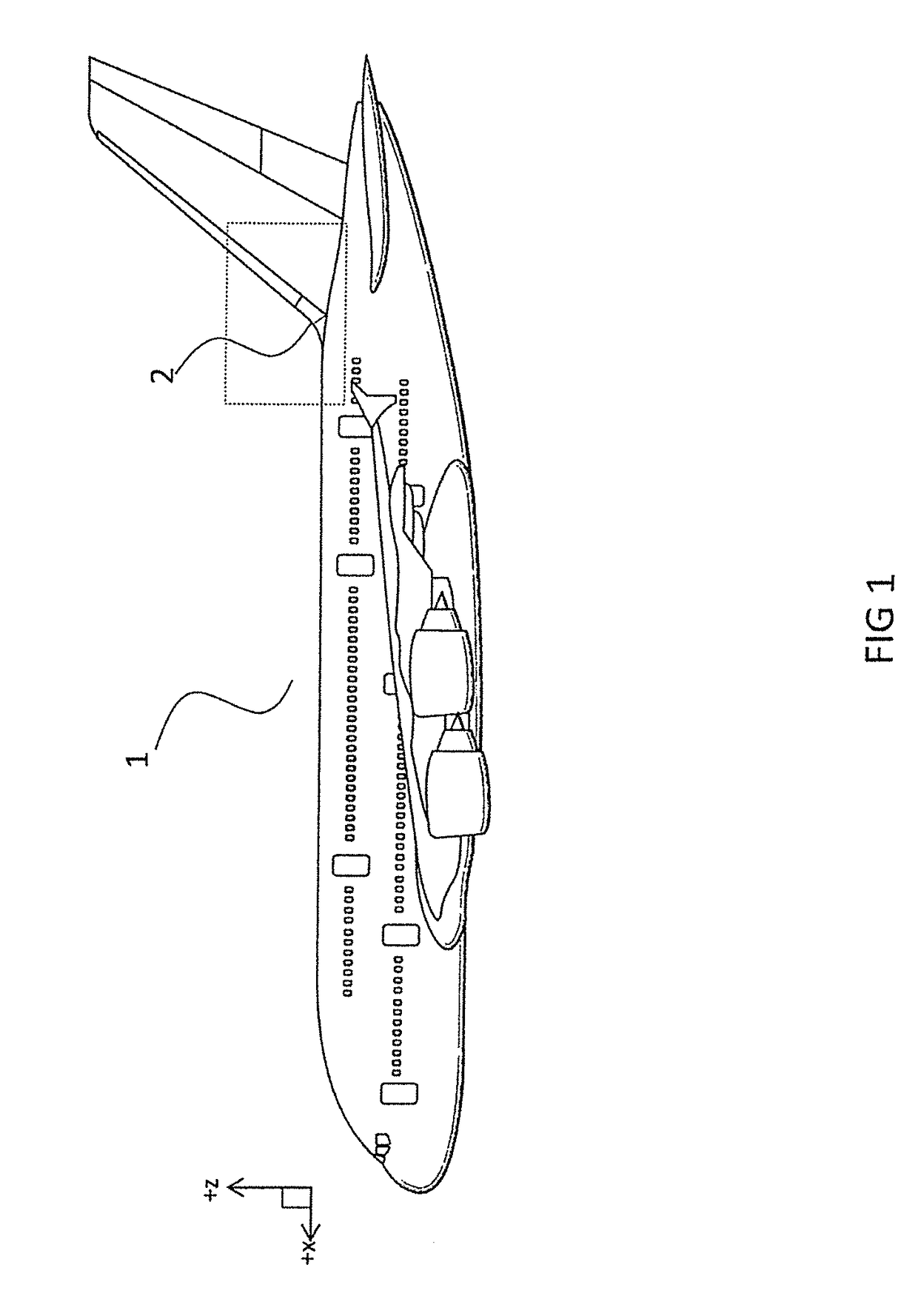
[0044]FIG. 1 shows a left-hand side view of an aircraft 1 comprising a type of fairing 2 according to a first embodiment of the present invention. The aircraft 1 is shown in flight in steady and level flight, i.e., during cruise phase of flight. FIG. 1 also provides a set of orthogonal axes which represent the aircraft longitudinal axis (X) and vertical axis (Z). The orthogonal aircraft lateral axis or spanwise axis (Y) is shown in more detail in FIG. 3.

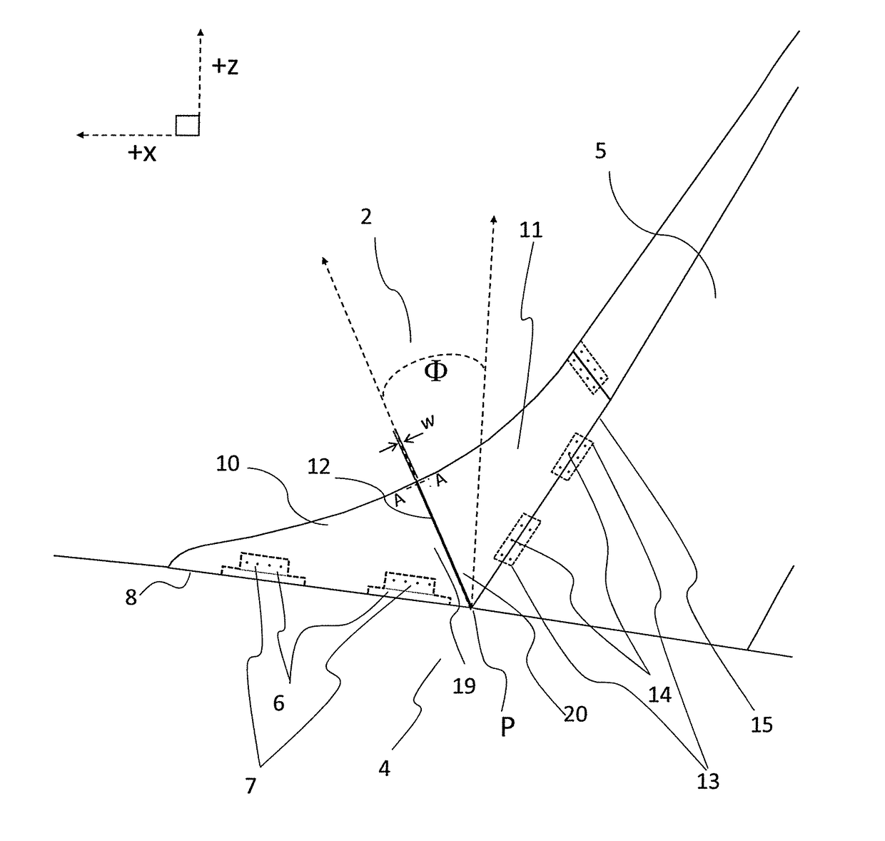
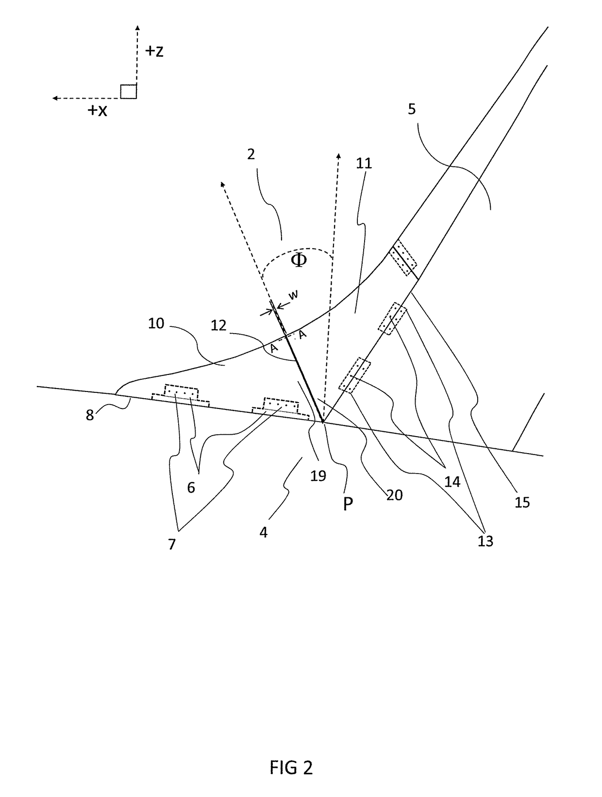
[0045]FIG. 2 shows a close-up left-hand side view of the fairing 2 and surrounding structure of FIG. 1 also with hidden detail that shows the attachment assemblies used to attach the fairing 2 to the surrounding structural components 4 and 5.

[0046]FIG. 3 shows a plan view of the fairing 2 of FIG. 2, again with the same hidden detail. It is shown also that the fairing 2 is symmetrical through a local fairing vertical plane lying on the aircraft X-Z plane.

[0047]From FIGS. 2 and 3, it is shown that the main body of the fairing 2 is comp...


PUM


Abstract

A fairing for an aircraft is disclosed in which the fairing comprises a first fairing portion configured to be fixedly attached to a first structural component and having a first edge; a second fairing portion configured to be fixedly attached to a second structural component and having a second edge, wherein the first edge and the second edge define an interface configured to enable relative movement between the first fairing portion and the second fairing portion.

Description

CROSS-REFERENCES TO RELATED APPLICATIONS[0001]This application claims the benefit of the European patent application No. 16196833.4 filed on Nov. 2, 2016, the entire disclosures of which are incorporated herein by way of reference.BACKGROUND OF THE INVENTION[0002]The present technology relates to a fairing for an aircraft.[0003]A fairing is a structure typically used for aircraft to covers gaps or spaces between structural components of an aircraft, for example between regions of the fuselage and the wing and / or the vertical and horizontal tail. Their primary purpose is to provide a smooth aerodynamic surface over the gaps and spaces that would otherwise occur in these regions, so that the airflow in the region is altered in a way to reduce overall aerodynamic drag.[0004]They are typically formed as single unitary components of composite material construction that are attached to surrounding structural components with attachment assemblies.[0005]The attachment assemblies typically c...

Claims


Application Information

Patent Timeline
Patent Type & Authority Applications(United States)
IPC IPC(8): B64C7/00B64C5/06
CPCB64C7/00B64C5/06F16J15/02
Inventor EILKEN, WOLFGANGTIRYAKI, MEMISSANMANN, KLAUS-PETERMOUSSAVI, GHASEM
Owner AIRBUS OPERATIONS GMBH
Why Eureka
Try Eureka