Electromagnetic navigation antenna assembly and electromagnetic navigation system including the same

a technology of electromagnetic navigation and antenna assembly, which is applied in the direction of resonant antennas, independent non-interfering antenna combinations, surgery, etc., can solve the problems of increasing the burden of generating electromagnetic field mapping, laborious and time-consuming process, and requiring expensive machines

Active Publication Date: 2018-05-03
TYCO HEALTHCARE GRP LP
View PDF4 Cites 4 Cited by
  • Summary
  • Abstract
  • Description
  • Claims
  • Application Information

AI Technical Summary

Benefits of technology

[0006]According to an aspect of the present disclosure, an antenna assembly for radiating at least one electromagnetic field for electromagnetic navigation is provided. The antenna assembly includes a substrate and a planar antenna including a trace that is deposited on the substrate and arranged in multiple loops. Respective distances between adjacent pairs of the loops increase in a direction from an innermost loop to an outermost loop.

Problems solved by technology

Generating such a mapping, however, requires taking precise electromagnetic field measurements at many (for example, hundreds of thousands or more) locations within the expected electromagnetic volume, which is a laborious and time-consuming process that, in some cases, requires expensive machines.
The burden of generating electromagnetic field mappings increases in circumstances where multiple antenna assemblies are employed.

Method used


Image

  • Electromagnetic navigation antenna assembly and electromagnetic navigation system including the same
  • Electromagnetic navigation antenna assembly and electromagnetic navigation system including the same
  • Electromagnetic navigation antenna assembly and electromagnetic navigation system including the same

Examples


Embodiment Construction

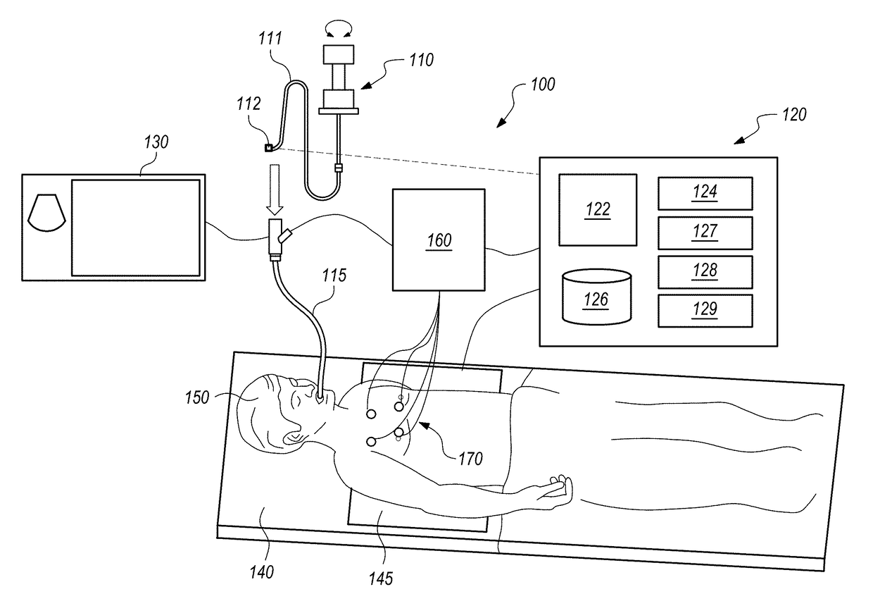
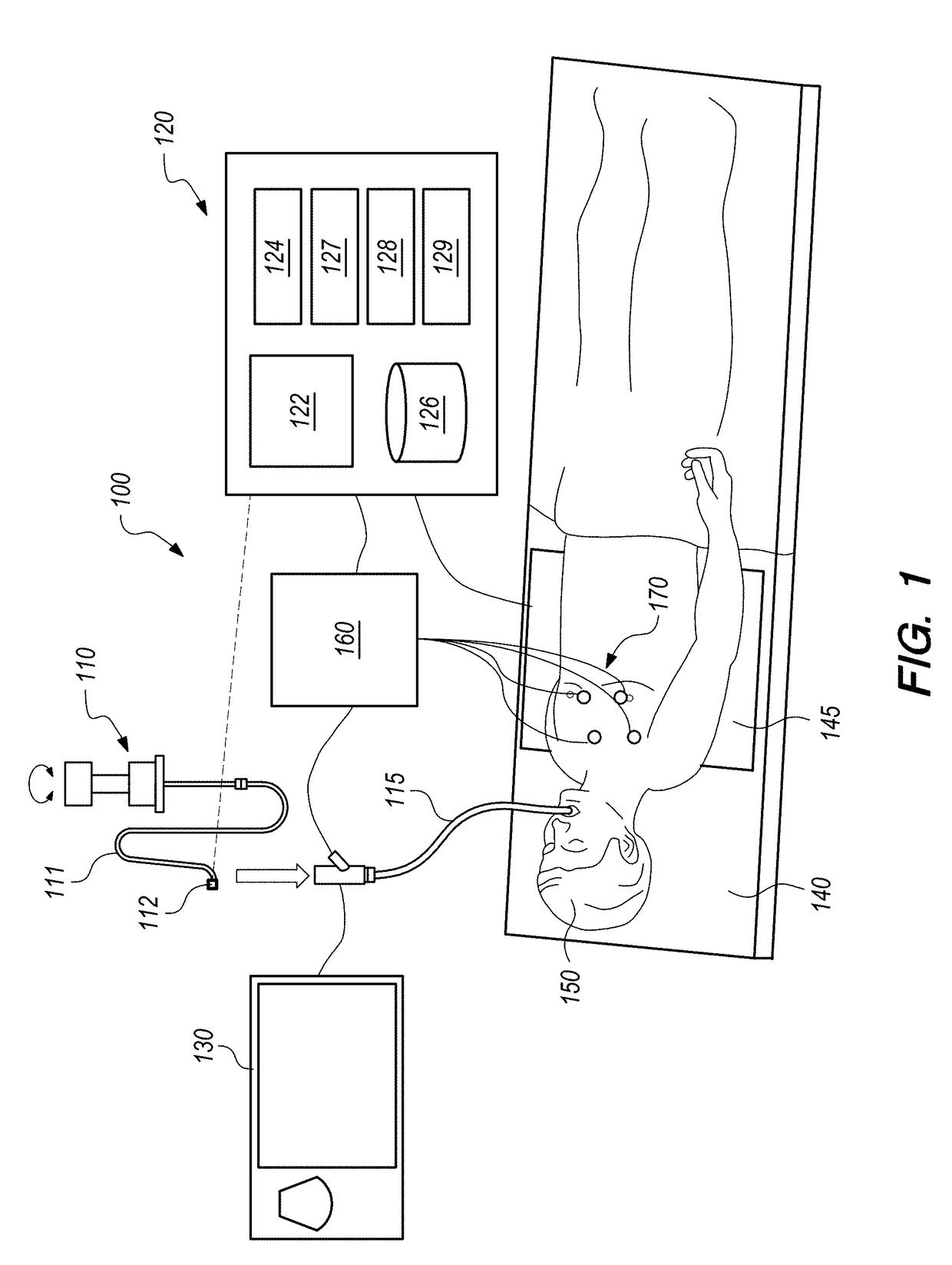
[0074]The present disclosure is directed to antenna assemblies for radiating electromagnetic fields for electromagnetic navigation, electromagnetic navigation systems that include such antenna assemblies, and computer-implemented methods of designing such antenna assemblies. In one example, by virtue of geometrical and other aspects of an antenna assembly herein, the need to generate and employ a detailed electromagnetic field mapping can be avoided by instead enabling an electromagnetic field mapping, theoretically computed based on characteristics of the antenna assembly, to be employed either alone or in conjunction with a more easily generated low-density electromagnetic field mapping obtained from measurements. In other words, the antenna assembly herein can serve as the basis upon which to generate an accurate high-density theoretical electromagnetic field mapping for EMN, without having to use expensive measuring equipment and without having to perform time-consuming and labo...


PUM


Abstract

An antenna assembly for radiating at least one electromagnetic field for electromagnetic navigation and an electromagnetic navigation system including such an antenna assembly are provided. The antenna assembly includes a substrate and a planar antenna including a trace that is deposited on the substrate and arranged in a plurality of loops. Respective distances between adjacent pairs of the loops increase in a direction from an innermost loop to an outermost loop.

Description

BACKGROUNDTechnical Field[0001]The present disclosure relates to antenna assemblies for electromagnetic navigation and methods for designing such antenna assemblies. More particularly, the present disclosure relates to antenna assemblies for radiating electromagnetic fields for electromagnetic navigation, electromagnetic navigation systems including such antenna assemblies, and computer-implemented methods of designing such antenna assemblies.Discussion of Related Art[0002]Electromagnetic (EM) navigation (EMN) has helped expand medical imaging, diagnosis, prognosis, and treatment capabilities by enabling a location and / or an orientation of a medical device to be accurately determined while the device is within the body of a patient. One example of a medical procedure in which EMN is employed is ELECTROMAGNETIC NAVIGATION BRONCHOSCOPY® (ENB™), which includes a planning phase and a navigation phase. During the planning phase, a computed tomography (CT) scan of the chest of the patient...

Claims


Application Information

Patent Timeline
Patent Type & Authority Applications(United States)
IPC IPC(8): H01Q9/04H01Q7/00H01Q1/22
CPCH01Q9/0457H01Q1/2258H01Q7/00H01Q1/2208H01Q21/28H01Q25/00A61B2017/00809A61B2034/2051A61B2034/2072A61B34/00H04B5/00
Inventor MORGAN, SEAN M.KOYRAKH, LEV A.
Owner TYCO HEALTHCARE GRP LP
Why Eureka
Try Eureka