Loudspeaker

Active Publication Date: 2018-05-03
BOGUSLAVSKIY EUGENY
View PDF7 Cites 0 Cited by
  • Summary
  • Abstract
  • Description
  • Claims
  • Application Information

AI Technical Summary

Benefits of technology

The patent describes a way to design a loudspeaker with multiple low-frequency emitting heads. These heads are placed close enough together to increase the crossover frequency, reduce distortion, and increase the acoustic load on the diffuser. This results in better uniformity of the signal and the ability to use filters of the first order in the frequency division of the signal. It is recommended that three or more emitting heads be used for better spatial characteristics, and that their emission axes be directed to one point for better concentration of sound waves and reduction of signal distortion.

Problems solved by technology

The disadvantage of such loudspeakers is low sensitivity, large phase distortion and uneven angular acoustic power.
The disadvantage of such a loudspeaker is the uneven angular acoustic power at the crossover frequency.

Method used


Image

  • Loudspeaker
  • Loudspeaker
  • Loudspeaker

Examples


Embodiment Construction

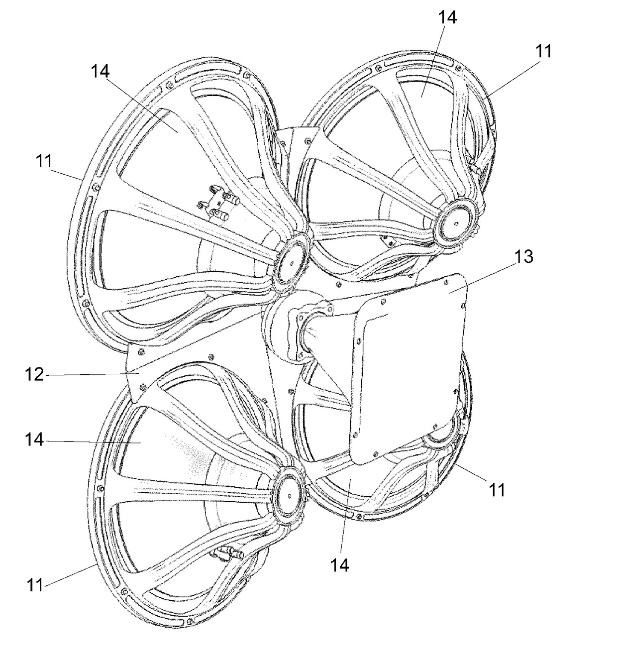
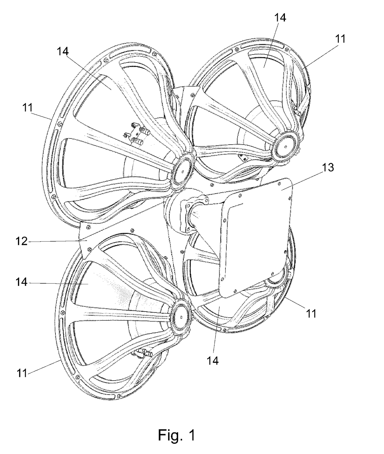
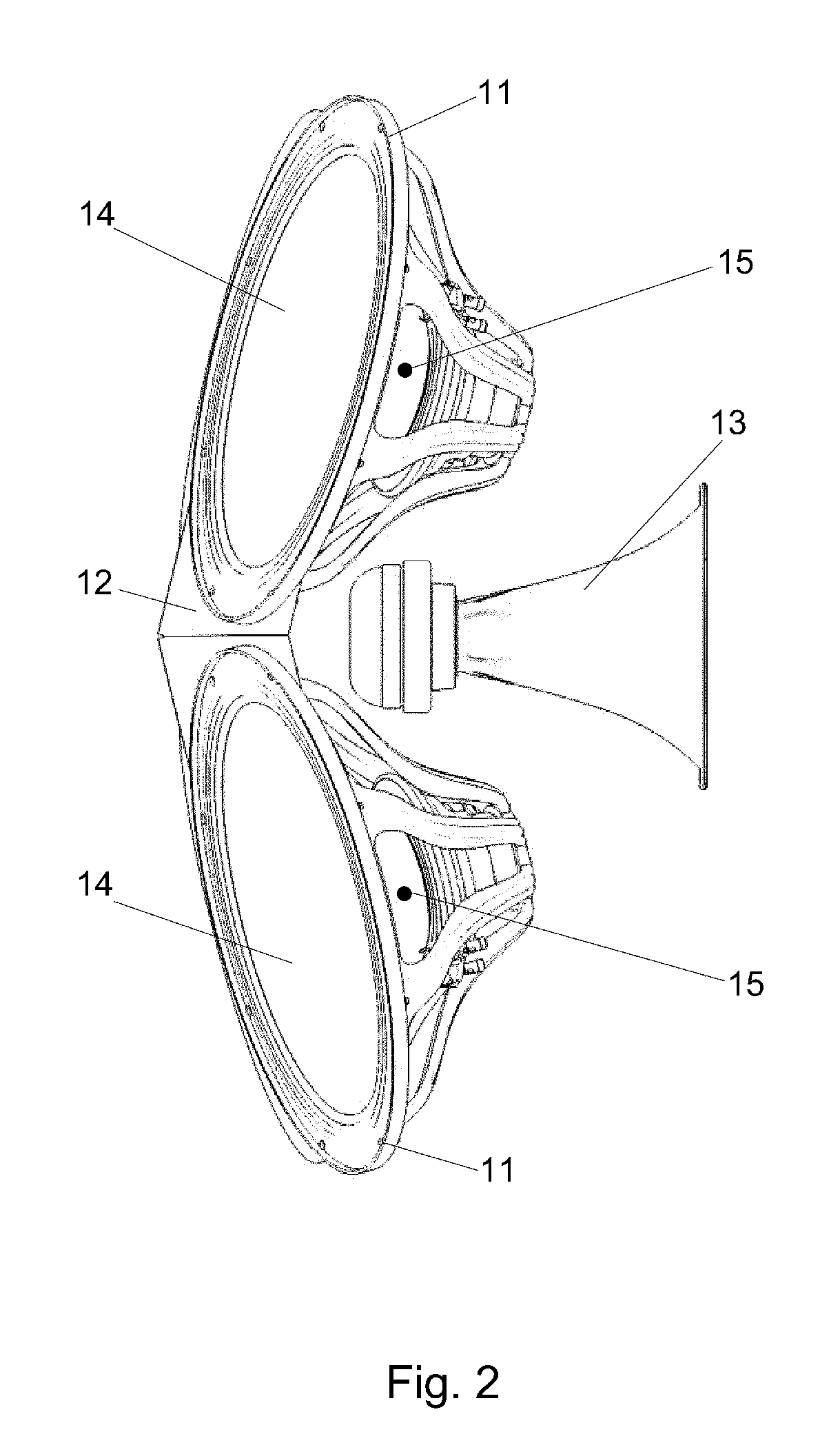
[0023]The loudspeaker shown in FIG. 1-3 contains four low-frequency emitting heads (11) with a diameter of 46 cm. The emitting heads are mounted on a rigid frame (12) close to each other and inclined at an angle of 12 degrees to the center of the loudspeaker. In the space between low-frequency emitting heads (11), a broadband emitting head (13) is installed. Low-frequency emitting heads (11) have conical diffusers (14), oriented with a convex side in the direction of the listener. Thus, the loudspeaker is an acoustic directional system.

[0024]The loudspeaker uses low-frequency emitting heads with conical diffusers. In such emitting heads, the acoustic center (15) or the center of the emission, as a rule, is located inside the cone of the diffuser, near its narrow part, often at a considerable distance from the aperture of the diffuser—the wide open end of the cone. In the traditional arrangement of the emitting heads with their aperture to the listener, the acoustic center (15) is lo...


PUM


Abstract

A loudspeaker comprising at least three first emitting heads (11) adapted to emit in a first frequency range, and at least one second emitting head (13) adapted to emit in a second frequency range, the first emitting heads (11) are located in close proximity to each other in the vertices of a virtual regular polygon with the number of vertices equal to the number of first emitting heads (11), and the second emitting head (13) is located in proximity to the geometric centre of said virtual polygon, wherein the first emitting heads have conical diffusers (14), oriented with their convex side in the direction of the listener, and the emission axes of the first emission heads are inclined at an angle (α) to a perpendicular drawn through the centre of the polygon, where the angle (α) is in a range of from 5 to 25 degrees.

Description

TECHNICAL FIELD[0001]The invention relates to the field of sound reproducing devices, and more particularly to loudspeakers.BACKGROUND ART[0002]It is known to use loudspeakers comprising a plurality of emitting heads, each of which is designed to reproduce sound in a certain frequency range, for example, an AC-35 loudspeaker produced by (p / o Radiotekhnika), which used three emitting heads, one for low frequencies, one for medium and one for high. The disadvantage of such loudspeakers is low sensitivity, large phase distortion and uneven angular acoustic power.[0003]The device described in U.S. Pat. No. 6,801,631 (DONALD J. NORTH) is known, which uses four low-frequency emitting heads located at the corners of a square and an additional head of a higher frequency range located between them.[0004]The disadvantage of such a loudspeaker is the uneven angular acoustic power at the crossover frequency.[0005]The closest to the proposed technical solution is the device disclosed in the desc...

Claims


Application Information

Patent Timeline
IPC IPC(8): H04R1/24H04R1/28H04R3/14
CPCH04R1/24H04R1/2811H04R3/14H04R1/26H04R1/403H04R19/02
Inventor JANEVICS, ROLANDS
Owner BOGUSLAVSKIY EUGENY
Why Eureka
Try Eureka