
Valve delivery system having an integral displacement component for managing chordae tendineae in situ and methods of use thereof

a technology of chordae tendineae and valve delivery system, which is applied in the field of valve prosthesis, can solve the problems of insufficiency or regurgitation, valve not opening properly, stenosis and insufficiency,

Active Publication Date: 2018-05-10
MEDTRONIC VASCULAR INC
View PDF6 Cites 24 Cited by
  • Summary
  • Abstract
  • Description
  • Claims
  • Application Information

AI Technical Summary

Benefits of technology

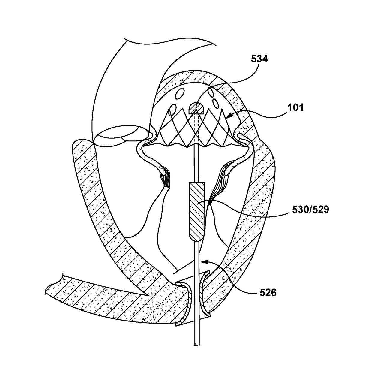
This patent describes a method of delivering a valve prosthesis to the heart to replace a damaged native valve. The valve is delivered using a system that includes a valve prosthesis and a displacement component. The displacement component is expanded to push chordae in the heart outward, creating space for the valve prosthesis. This allows the valve to be positioned correctly and deployed into apposition with the native valve. Overall, this method improves the accuracy and effectiveness of valve replacement surgeries.

Problems solved by technology

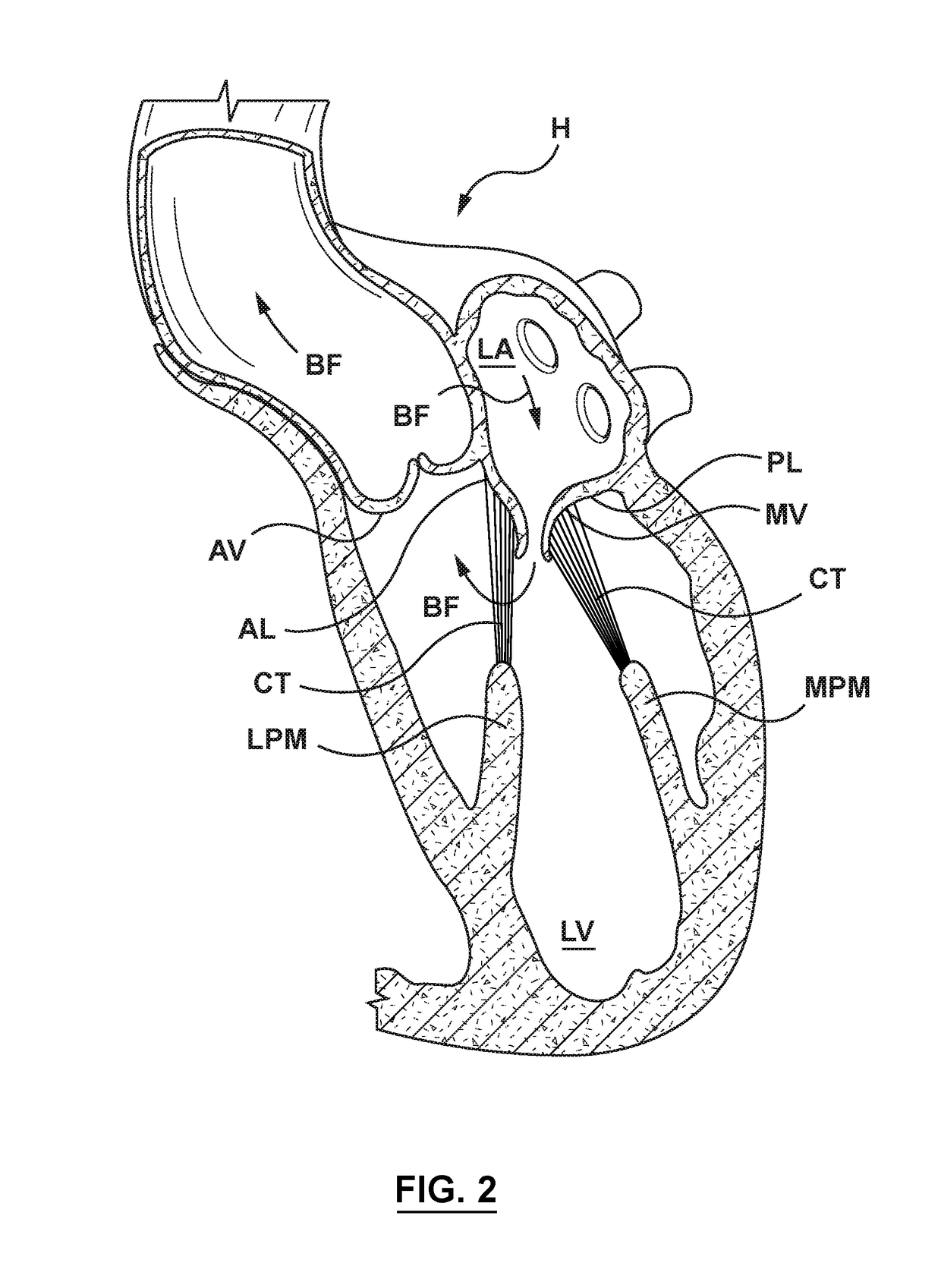
Problems that may develop with valves include stenosis in which a valve does not open properly, and / or insufficiency or regurgitation in which a valve does not close properly.
Stenosis and insufficiency may occur concomitantly in the same valve.
The effects of valvular dysfunction vary, with mitral regurgitation or backflow typically having relatively severe physiological consequences to the patient.
However, during such a transapical approach, the chordae tendineae may act as an obstacle within the delivery pathway.
Chordae tendineae are not all aligned the same way making the delivery pathway to the mitral valve more challenging.
The valve delivery system may become entangled in chordae tendineae during advancement, thereby restricting movement of the valve delivery system within the anatomy and also preventing accurate alignment and / or deployment of the valve prosthesis.

Method used


Image

  • Valve delivery system having an integral displacement component for managing chordae tendineae in situ and methods of use thereof
  • Valve delivery system having an integral displacement component for managing chordae tendineae in situ and methods of use thereof
  • Valve delivery system having an integral displacement component for managing chordae tendineae in situ and methods of use thereof

Examples


Embodiment Construction

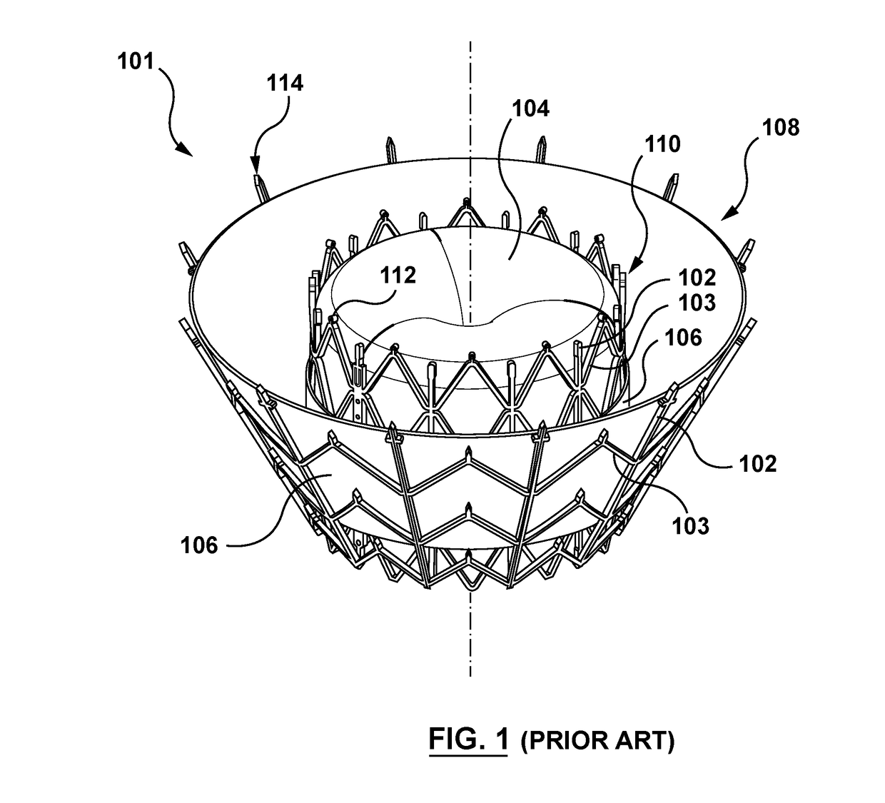
[0049]Specific embodiments of the present invention are now described with reference to the figures, wherein like reference numbers indicate identical or functionally similar elements. Unless otherwise indicated, the terms “distal” and “proximal” are used in the following description with respect to a position or direction relative to the treating clinician. “Distal” and “distally” are positions distant from or in a direction away from the clinician, and “proximal” and “proximally” are positions near or in a direction toward the clinician. In addition, the term “self-expanding” is used in the following description and is intended to convey that the structures are shaped or formed from a material that can be provided with a mechanical memory to return the structure from a compressed or constricted delivery configuration to an expanded deployed configuration. Non-exhaustive exemplary self-expanding materials include stainless steel, a pseudo-elastic metal such as a nickel titanium all...


PUM


Abstract

Embodiments hereof relate methods of delivering a valve prosthesis to an annulus of a native valve of a heart. A valve delivery system is introduced into a ventricle of the heart via a ventricular wall of the heart. The valve delivery system has a displacement component at the distal portion thereof. The valve prosthesis is in a delivery configuration and the displacement component is in a delivery state in which the displacement component has a first outer diameter. While the valve prosthesis is in the delivery configuration, the displacement component of the valve delivery system is radially expanded into an expanded state in which the displacement component has a second outer diameter greater than the first outer diameter. The valve delivery system is advanced towards the annulus of the native valve of the heart with the displacement component in the expanded state to displace chordae tendineae.

Description

FIELD OF THE INVENTION[0001]The invention relates to valve prostheses and more particularly to valve delivery systems configured to manage chordae tendineae during delivery of valve prostheses in situ.BACKGROUND OF THE INVENTION[0002]A wide range of medical treatments are known that utilize “endoluminal prostheses.” As used herein, endoluminal prostheses are intended to include medical devices that are adapted for temporary or permanent implantation within a body lumen, including both naturally occurring and artificially made lumens. Examples of lumens in which endoluminal prostheses may be implanted include but are not limited to arteries, veins, gastrointestinal tract, biliary tract, urethra, trachea, hepatic and cerebral shunts, and fallopian tubes.[0003]Stent prostheses are known for implantation within a body lumen for providing artificial radial support to the wall tissue that defines the body lumen. To provide radial support to a blood vessel, such as one that has been widene...

Claims


Application Information

Patent Timeline
Patent Type & Authority Applications(United States)
IPC IPC(8): A61F2/24
CPCA61F2/243A61F2/2418A61F2210/0014A61F2/2433A61F2/2436A61F2250/0003
Inventor WHITE, FRANKJONES, TIMANDERSON, MARCFRISBY, PARAICKEANE, EMMAVAUGHAN, BRENDAN
Owner MEDTRONIC VASCULAR INC
Learn More