Apparatus and system for dynamic acoustic locking ceiling system and methods thereof

a technology of dynamic acoustic locking and ceiling baffles, applied in the direction of instruments, buildings, building components, etc., can solve the problems of causing acoustic problems in the ceiling, affecting the sound quality of the room, etc., to and reduce unwanted noise or room acoustics

Active Publication Date: 2018-05-10
TURF DESIGN INC
View PDF9 Cites 14 Cited by
  • Summary
  • Abstract
  • Description
  • Claims
  • Application Information

AI Technical Summary

Benefits of technology

[0014]The present disclosure further relates to an improved method of installing the locking ceiling baffles and creating the dynamic acoustic locking ceiling system, in which the acoustic locking ceiling baffles are installed into the ceiling structure by pushing the locking mechanism into the existing ceiling hanger, such as the standard UNISTRUT® metal framing system, without the need for additional tools, clips or additional attachment devices, to provide an aesthetically pleasing image, and to function to reduce unwanted noise or room acoustics.
[0015]The present disclosure also relates to an improved method of installing the locking ceiling baffles and creating the dynamic acoustic locking ceiling system, in which the acoustic locking ceiling baffles are snapped or attached to the ceiling structure through the use of magnets and magnetic attraction, such that magnets strategically embedded in the ceiling baffle in a location that once constructed, the ceiling baffle can be affixed to the existing ceiling hanger, such as the standard UNISTRUT® metal framing system, using the magnets and without the need for additional tools, clips or additional attachment devices, to provide an aesthetically pleasing image, and to function to reduce unwanted noise or room acoustics.
[0016]It is thus an objective of the present disclosure to provide an improved acoustic locking ceiling baffle, comprising a sing...

Problems solved by technology

However, either for cost or design purposes, many designs provide that the mechanical and electrical equipment are to be seen and not hidden.
Although the exposed ceiling may be a function...

Method used


Image

  • Apparatus and system for dynamic acoustic locking ceiling system and methods thereof
  • Apparatus and system for dynamic acoustic locking ceiling system and methods thereof
  • Apparatus and system for dynamic acoustic locking ceiling system and methods thereof

Examples


Embodiment Construction

[0041]As stated herein, the objective of the present disclosure is to provide an improved acoustic locking ceiling baffle, and an improved dynamic acoustic locking ceiling system, along with improved methods for installing the locking ceiling baffles and creating the dynamic acoustic locking ceiling system.

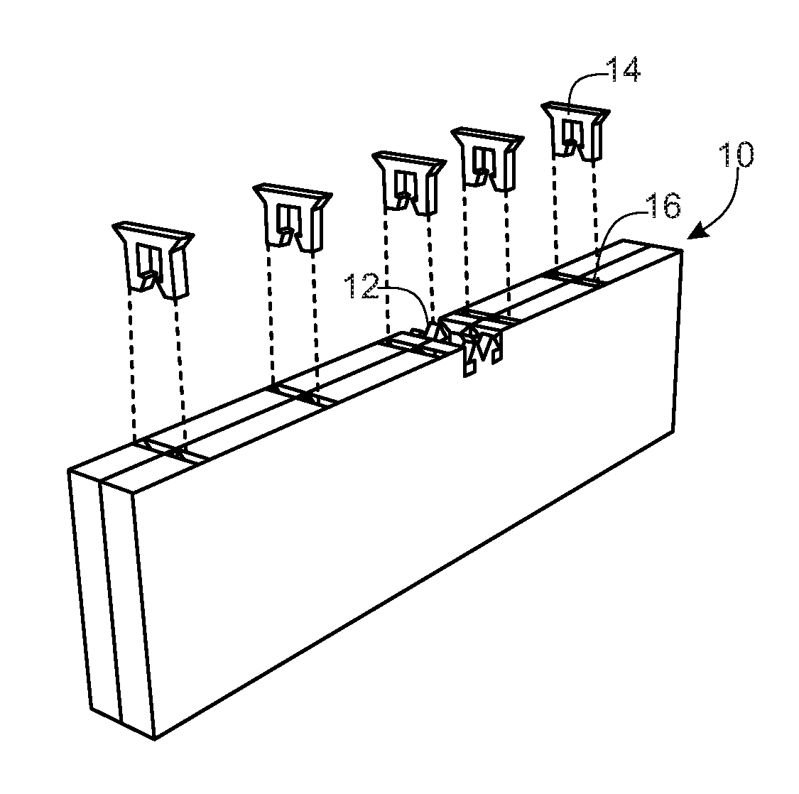
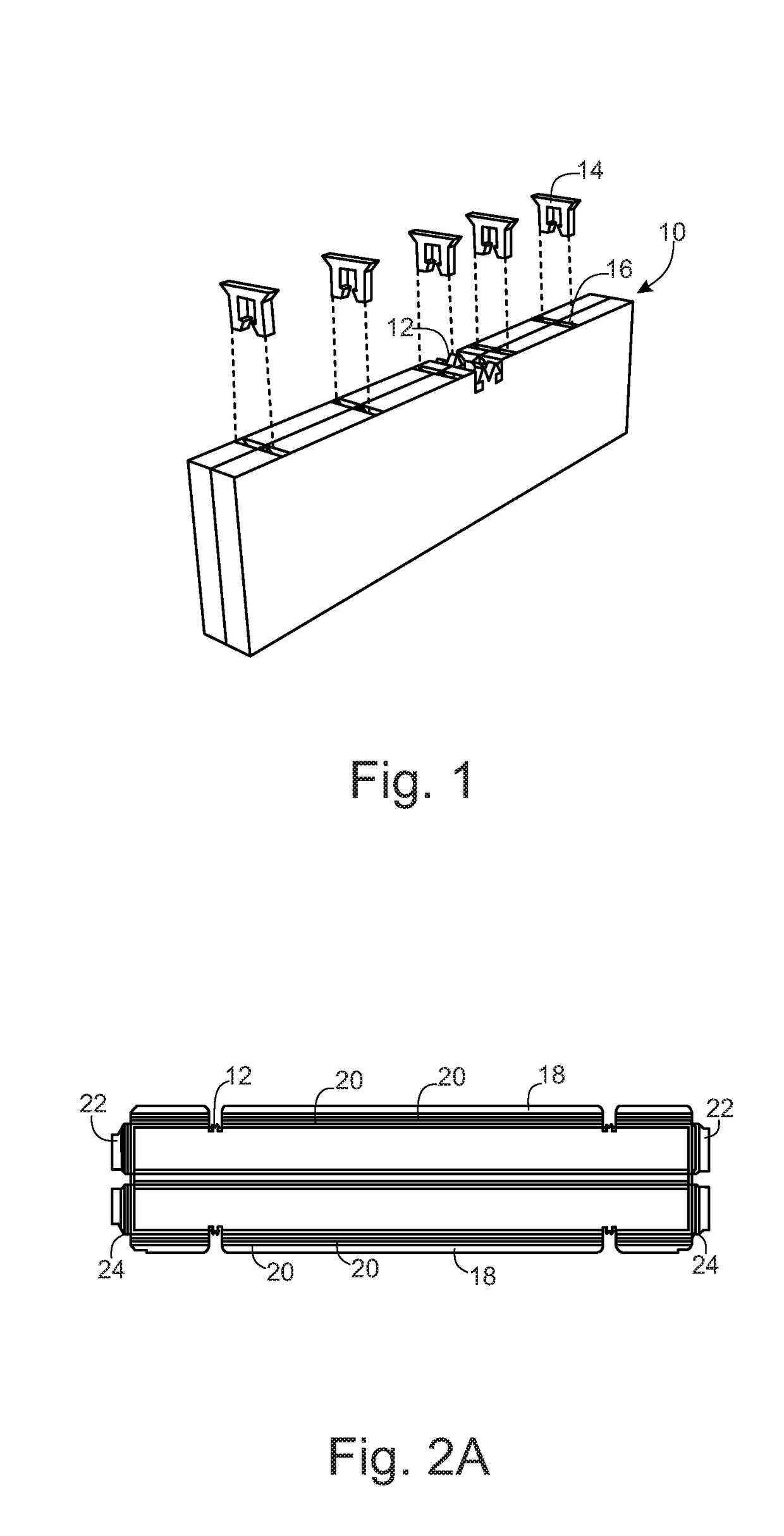
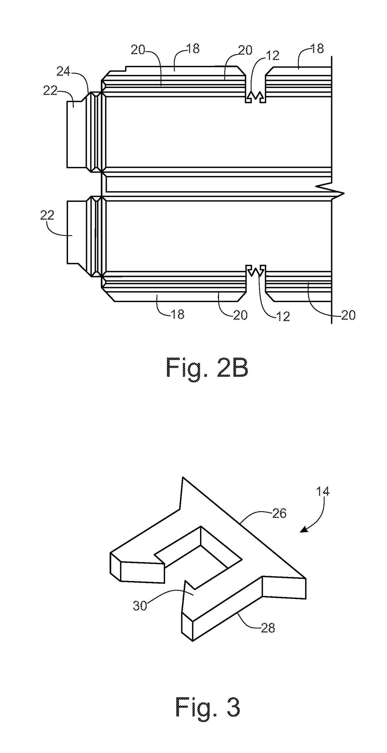
[0042]Referring to the drawings, wherein like reference numerals refer to the same or similar features in the various views, FIGS. 1 through 6 show different views of the improved locking baffle 10. FIG. 1 shows the resulting baffle 10 after being folded into shape, resulting in a locking mechanism 12 at the top of the ceiling baffle 10. The ceiling baffle 10, which is made in the preferred embodiment, from a single sheet of 9 mm polyester felt or PET Felt, and is intended to be folded into a rectangular or a slab shape, approximately 88 inches long, 8.68 inches high and 2.125 inches thick. One example for holding the slab baffle 10 in its shape includes the use of one or more loc...


PUM


Abstract

A dynamic acoustic locking ceiling baffle and a dynamic acoustic locking ceiling system, that includes a single piece of material folded into acoustic locking ceiling baffles, using locking pieces and locking mechanisms, to quickly and easily install the acoustic locking ceiling baffle onto construction ceiling hangers to provide an aesthetically pleasing image, along with a reduction in unwanted noise or room acoustics.

Description

[0001]The present application claims priority to U.S. Provisional Patent Application Ser. No. 62 / 357,066, filed Jun. 30, 2016, entitled “Apparatus And System For Dynamic Acoustic Locking Ceiling System And Methods Thereof”, U.S. Provisional Patent Application Ser. No. 62 / 357,026, filed Jun. 30, 2016, and entitled “Apparatus And System For Dynamic Acoustic Ceiling System And Methods Thereof”, U.S. Provisional Patent Application Ser. No. 62 / 517,640, filed Jun. 9, 2017, and entitled “Ceiling Baffle Apparatus And Ceiling Baffle System For A Dynamic Acoustic Ceiling And Methods Thereof”, and U.S. Provisional Patent Application Ser. No. 62 / 518,347, filed Jun. 12, 2017, entitled “Apparatus And System For Dynamic Acoustic Locking Ceiling System And Methods Thereof”, all of which are hereby incorporated by reference in their entirety.BACKGROUNDa. Technical Field[0002]The instant disclosure relates to locking ceiling baffles, a system for dynamic acoustic locking ceiling baffles, along with t...

Claims


Application Information

Patent Timeline
IPC IPC(8): E04B9/00G10K11/162E04B9/04E04B1/84
CPCE04B9/001G10K11/162E04B9/0414E04B1/84E04B2001/829E04B9/064E04B9/366E04B9/045G10K11/168
Inventor GILLETTE, JASONCHIU, KUAN-WEN
Owner TURF DESIGN INC
Why Eureka
Try Eureka