Ceiling baffle apparatus and ceiling baffle system for a dynamic acoustic ceiling and methods thereof

a dynamic acoustic ceiling and ceiling baffle technology, applied in the direction of instruments, buildings, building components, etc., can solve the problems of causing acoustic problems in the ceiling, affecting the sound quality of the room, etc., to and reduce unwanted noise or room acoustics

Active Publication Date: 2018-05-10
TURF DESIGN INC
View PDF13 Cites 7 Cited by
  • Summary
  • Abstract
  • Description
  • Claims
  • Application Information

AI Technical Summary

Benefits of technology

[0016]It is thus an objective of the present disclosure to provide an improved acoustic ceiling baffle, comprising a locking mechanism made of the same material as the baffle and which allows for the baffle to be installed into an existing ceiling hanger without the need for tools, clips or additional attachment devices.
[0017]It is yet another object of the present disclosure to provide an improved dynamic acoustic ceiling system in which the impr

Problems solved by technology

However, either for cost or design purposes, many designs provide that the mechanical and electrical equipment are to be seen and not hidden.
Although the exposed ceiling may be a function of

Method used


Image

  • Ceiling baffle apparatus and ceiling baffle system for a dynamic acoustic ceiling and methods thereof
  • Ceiling baffle apparatus and ceiling baffle system for a dynamic acoustic ceiling and methods thereof
  • Ceiling baffle apparatus and ceiling baffle system for a dynamic acoustic ceiling and methods thereof

Examples


Embodiment Construction

[0055]As stated herein, the objective of the present disclosure is to provide an improved acoustic ceiling baffle 10, and an improved dynamic acoustic ceiling system 100, along with improved methods for facilitating the installation of the ceiling baffles 10 and creating the dynamic acoustic ceiling system 100.

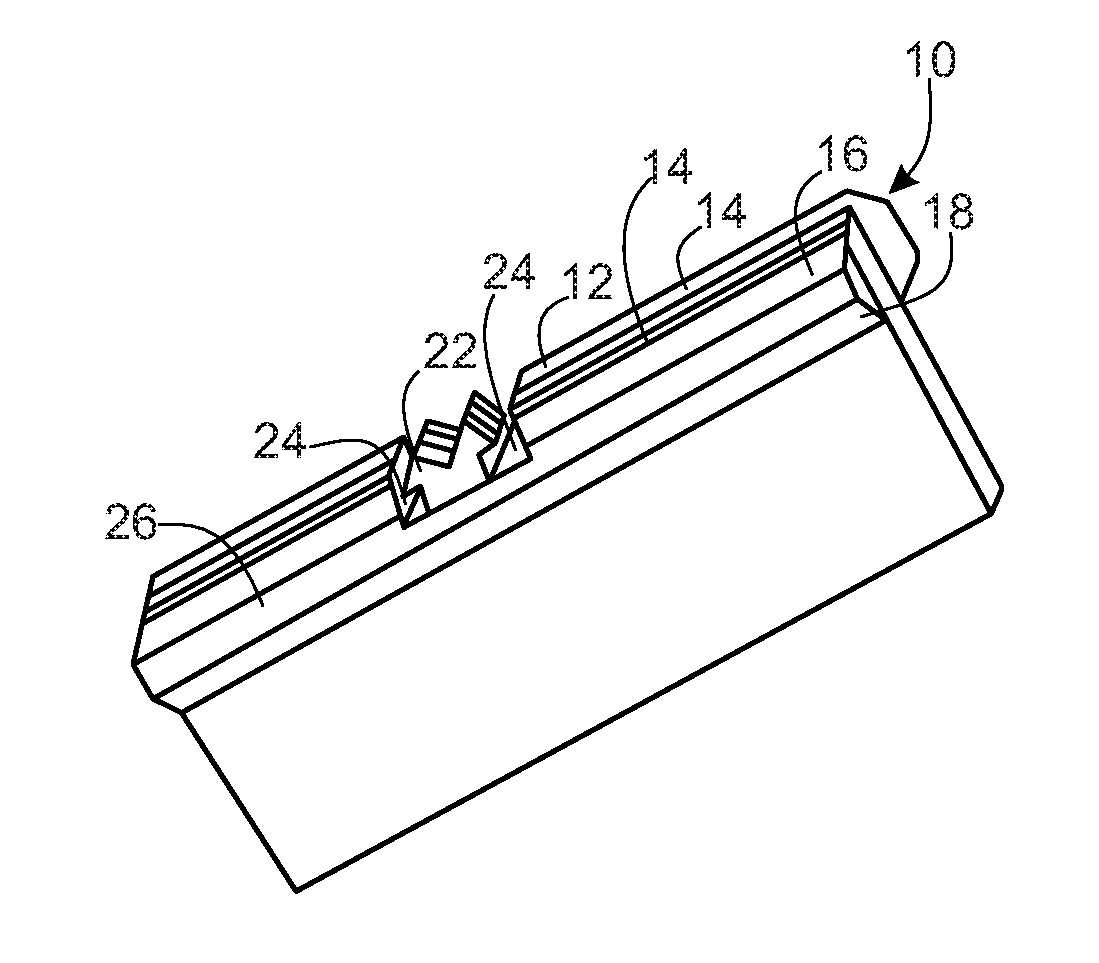
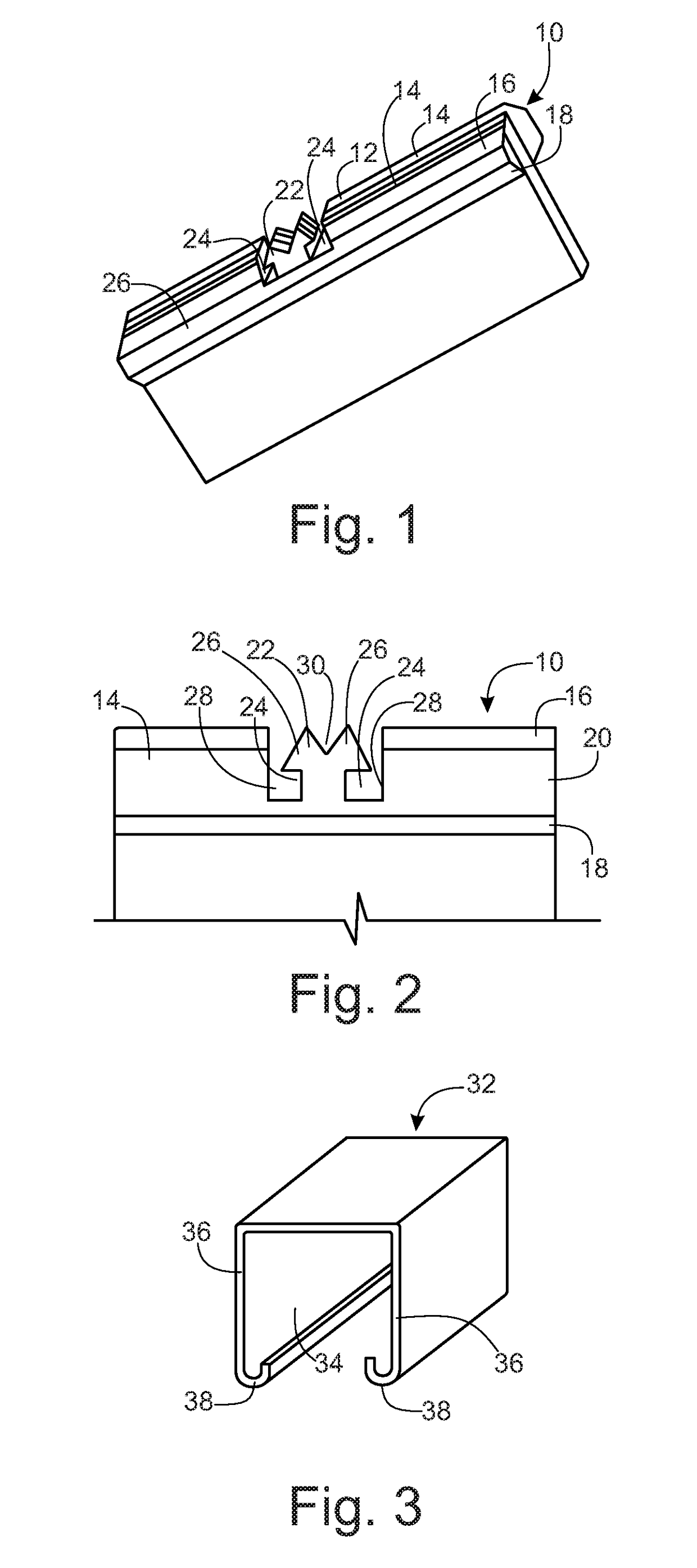
[0056]Referring to the drawings, wherein like reference numerals refer to the same or similar features in the various views, and FIGS. 1, 2 and 4 through 10 show different views of the preferred embodiment of the improved ceiling baffle 10. In particular, FIG. 1 shows an improved ceiling baffle 10, which comprises three pieces of material 12, 14, laminated together. Each of the pieces are made of polyester felt or PET Felt (although other material may be used), with a middle portion 12 being 48 inches long, between 7 inches and 9.5 inches high (with varying heights throughout the length, depending on the particular baffle design) and 9 mm thick. FIGS. 11 through 16 and 26 thro...


PUM


Abstract

A dynamic acoustic ceiling baffle and a dynamic acoustic ceiling baffle system, that includes multiple shaped baffles that can be quickly and easily installed onto construction ceiling hangers without the need for additional tools, to provide an aesthetically pleasing image, such as an undulating image, along with a reduction in unwanted noise or room acoustics.

Description

[0001]The present application is a continuation of and claims priority to U.S. Provisional Patent Application Ser. No. 62 / 357,026, filed Jun. 30, 2016, and entitled “Apparatus And System For Dynamic Acoustic Ceiling System And Methods Thereof”, U.S. Provisional Patent Application Ser. No. 62 / 357,066, filed Jun. 30, 2016, entitled “Apparatus And System For Dynamic Acoustic Locking Ceiling System And Methods Thereof”, U.S. Provisional Patent Application Ser. No. 62 / 517,640, filed Jun. 9, 2017, and entitled “Ceiling Baffle Apparatus And Ceiling Baffle System For A Dynamic Acoustic Ceiling And Methods Thereof”, and U.S. Provisional Patent Application Ser. No. 62 / 518,347, filed Jun. 12, 2017, entitled “Apparatus And System For Dynamic Acoustic Locking Ceiling System And Methods Thereof”, all of which are hereby incorporated by reference in their entirety.BACKGROUNDa. Technical Field[0002]The instant disclosure relates to ceiling baffles, ceiling baffle systems for a dynamic acoustic ceil...

Claims


Application Information

Patent Timeline
IPC IPC(8): E04B9/00G10K11/168E04B9/04E04B1/84
CPCE04B9/001G10K11/168E04B9/045E04B1/84E04B2001/829E04B9/064E04B9/366G10K11/162E04B9/0414
Inventor GILLETTE, JASONHEADLEY, DUSTIN
Owner TURF DESIGN INC
Why Eureka
Try Eureka