Extended leg return elbow for use with a steel making furnace and method thereof

Active Publication Date: 2018-05-10
AMERIFAB INC
View PDF7 Cites 2 Cited by
  • Summary
  • Abstract
  • Description
  • Claims
  • Application Information

AI Technical Summary

Benefits of technology

The present patent describes a cooling panel for a steel making furnace that includes a plurality of sections of piping and a plurality of 180-degree shaped return elbows. The cooling panel is designed to be mounted to the inner wall of the furnace and includes an inlet for receiving a fluid for cooling the furnace and an outlet for exhausting gases. The cooling panel is formed by welding the sections of piping to the return elbows during an automatic or semi-automatic welding process. The technical effect of this design is to provide an improved cooling panel that allows for efficient cooling of the furnace without deformation of the panel at high temperatures.

Problems solved by technology

Although water-cooled panels last longer than the brick refractory they replaced, the panels have serious problems with wear and are subject to damage.
This unscheduled downtime can have serious repercussions throughout the steel mill.
Such interruptions also decrease production and significantly increase operating expenses.
Also, making unscheduled repairs to the furnace panels constitutes a considerable percentage of maintenance expenses.

Method used


Image

  • Extended leg return elbow for use with a steel making furnace and method thereof
  • Extended leg return elbow for use with a steel making furnace and method thereof
  • Extended leg return elbow for use with a steel making furnace and method thereof

Examples


Embodiment Construction

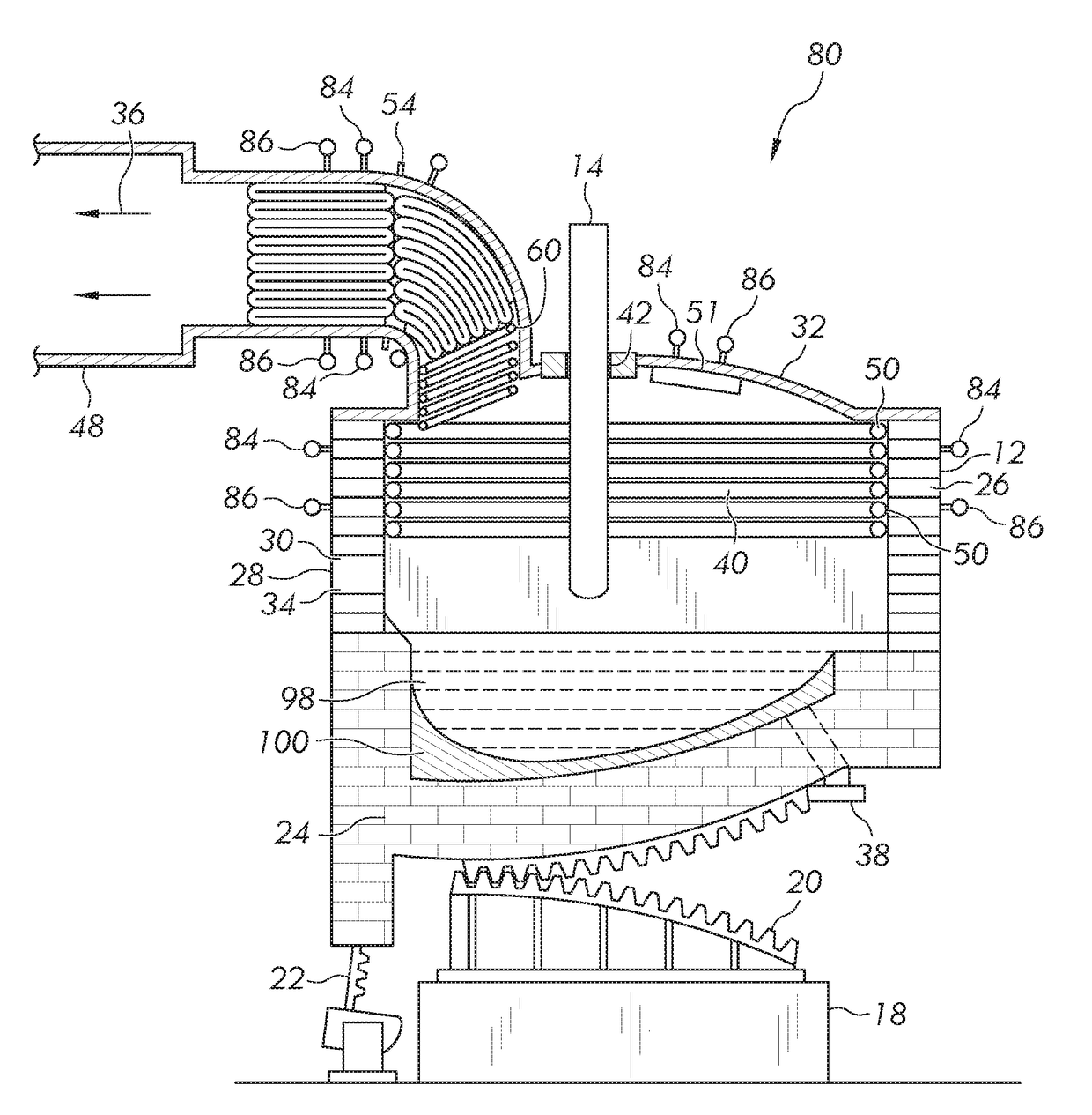
[0018]In an electric arc furnace (EAF), a portion above a hearth or smelting area must be protected against the high internal temperatures of the furnace. The EAF vessel wall, cover or roof and duct work are particularly at risk from massive thermal, chemical, and mechanical stresses caused by charging the steel. Such stresses greatly limit the operational life of the furnace. The EAF is generally designed and fabricated as a welded steel structure which is protected against the high temperatures inside the furnace vessel by a refractory lining and water cooled panels. Water-cooled roof panels and water-cooled sidewall panels are located in portions of the furnace vessel above the melting / smelting area of the furnace.

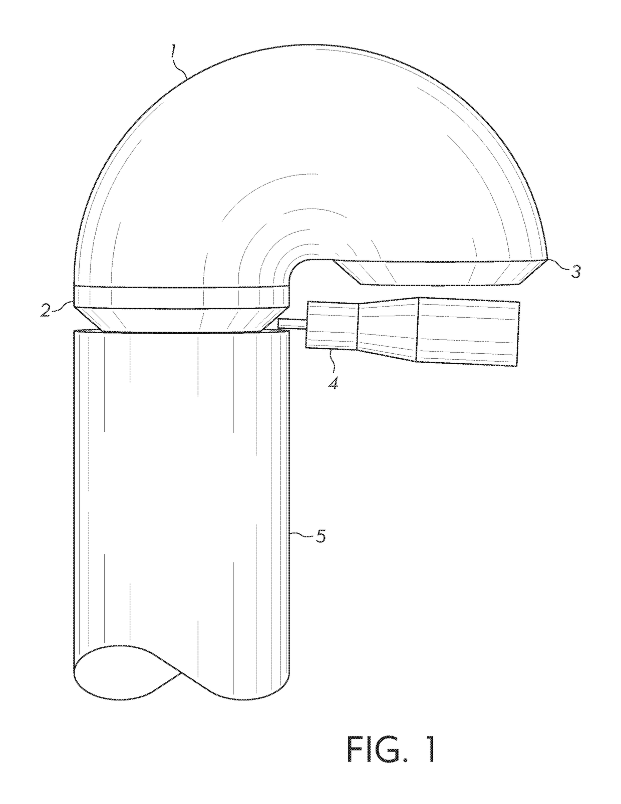
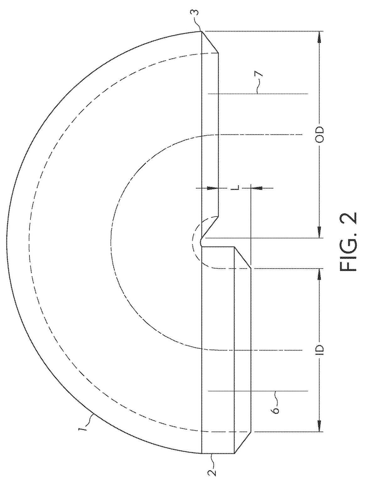
[0019]In addition, furnace off-gas ducts are also comprised of a plurality of pipe around its circumference that protect the ductwork from the high temperatures and caustic gases produced during furnace operation. Existing water-cooled panels and ducts are made both wit...


PUM


Abstract

A 180-degree pipe elbow having one end extending beyond the other end and method of joining a 180-degree pipe elbow to lengths of cooling pipe to form a cooling panel for use in a furnace, boiler or other industrial heating apparatus that benefits from assistance of a cooling panel. Having one end of the elbow extend beyond the other end of the elbow enables the one end to be joined to a length of pipe by welding whereby the joining may be by automatic welding which will reduce manufacturing costs and ensure a quality weld.

Description

RELATED APPLICATIONS[0001]This application claims the benefit of U.S. Provisional Application Ser. No. 62 / 419,995, filed Nov. 10, 2016, the disclosure of which is hereby incorporated by reference in its entirety.FIELD OF THE DISCLOSURE[0002]The present disclosure relates to a method and an apparatus for making and repairing cooling pipe(s) used in the operational life of industrial piping systems and metallurgical furnaces (e.g., metal melting / smelting and refining furnaces), boilers, heat changers, and systems components such as roofs, duct work, dust evacuation system components, and any other component requiring heat removal. More particularly, the invention relates to making and / or repair of water cooled equipment that are often designed with a plurality of pipe welded together and require 180 degree returns welded to the pipe ends to complete proper serpentine water flow through the pipes comprising the water cooled equipment.BACKGROUND OF THE INVENTION[0003]Cooling of industri...

Claims


Application Information

Patent Timeline
IPC IPC(8): F27D1/12F16L43/00
CPCF27D1/12F16L43/001F27D2001/0059F27D2001/0079F27B3/24F27B1/24F27D9/00F27D2009/0018F27D2009/0024
Inventor MANASEK, RICHARD J.
Owner AMERIFAB INC
Why Eureka
Try Eureka