VTOL airplane or drone utilizing at least two tilting propellers located in front of wings center of gravity.

a technology of vtol aircraft and vtol drone, which is applied in the direction of vertical landing/take-off aircraft, aircraft navigation control, transportation and packaging, etc., can solve the problems of v-22 osprey, complex and expensive aircraft,

Inactive Publication Date: 2018-05-24
WALL KEITH
View PDF2 Cites 17 Cited by
  • Summary
  • Abstract
  • Description
  • Claims
  • Application Information

AI Technical Summary

Benefits of technology

[0005]In one embodiment the wings ailerons would be slaved to the tilting propellers. The ailerons would be of sized or located sufficiently outside of the propeller slipstream to have negligible effect on the pitching authority of the aircraft. They would be slaved to the tilting propeller in a way that when the propeller is rotated up words that the aileron would rotate down words and vice versa when the propeller is rotated downward the aileron would rotate upwards. This will allow the tilting propellers to provid

Problems solved by technology

This results in an aircraft that is either complex and expensive like the V-22 Osprey or worse wit

Method used


Image

  • VTOL airplane or drone utilizing at least two tilting propellers located in front of wings center of gravity.
  • VTOL airplane or drone utilizing at least two tilting propellers located in front of wings center of gravity.
  • VTOL airplane or drone utilizing at least two tilting propellers located in front of wings center of gravity.

Examples


Embodiment Construction

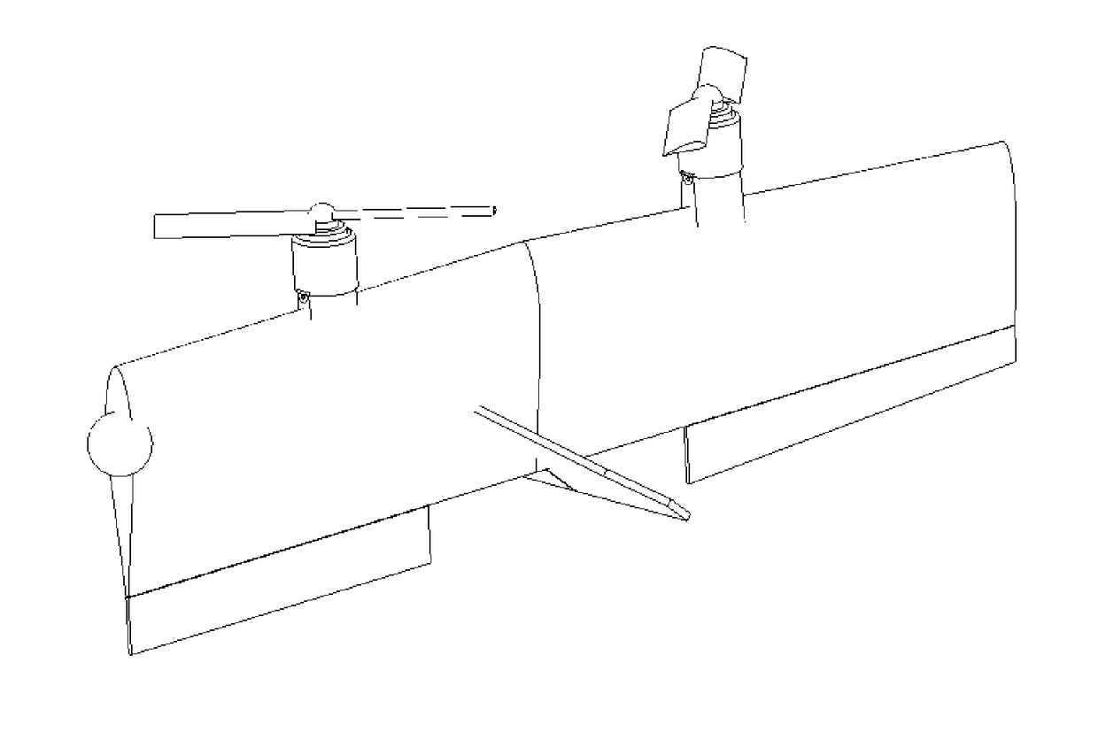
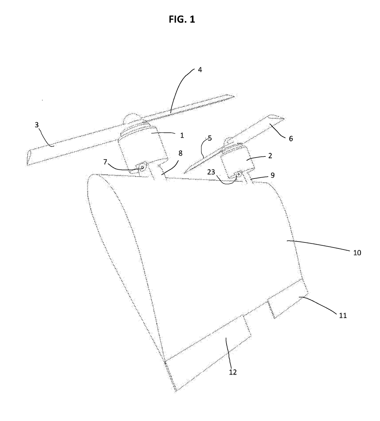
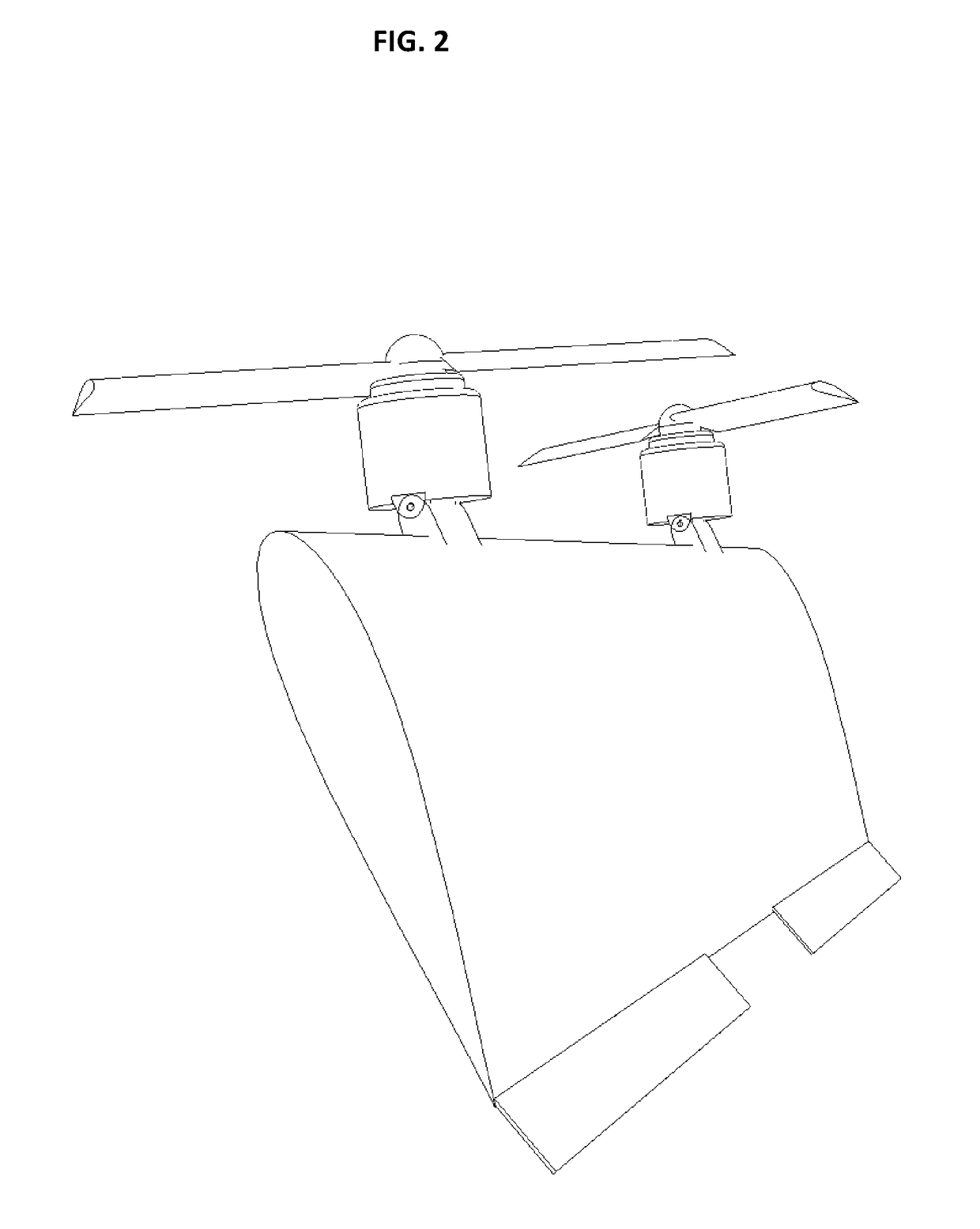
[0025]This VTOL aircraft has tilting propellers that are actively controlled view flight computer or mechanical mixer. They allow for an aircraft to take off vertical maintaining control throughout the flight envelop. By active control it is meant that there is means built in the aircraft to allow for the propellers to tilt for example by a hinge 7 that attaches the propeller assembly to the aircraft. There is also a means to move this propeller assembly for example a servo 15. Though any means that is capable of moving this assemble with speed and procession for example hydraulic, jack screw or other mechanical device.

[0026]FIG. 1 shows the basic wing configuration regardless of the application. For example any configuration would have at least two actively controlled tilting propeller located in front of the wing surface of the for example. This wing could be located on a tiltwing aircraft FIG. 4 box wing aircraft other molt wing aircraft. Alternatively it be a tell siting aircraf...


PUM


Abstract

A vertical take-off and landing aircraft or drone that has at least two tilting propellers mounted in front of the center of gravity of the wing. These tilting propeller are actively controlled and are capable of providing pitch, roll and yaw control throughout the flight envelop. This method of control can be applied to tilt wing or teal sitter aircraft, conventional or flying wing as well as other wing configuration for example box wing. In hovering flight the wing would be in the vertical position. The tilting propeller would provide pitch and yaw control. Roll control would be provided by differential thrust of the propellers. As the aircraft transitions to forward flight pitch control would be provided by tilting propeller. While yaw and roll control would be provided by a combination of tilting propellers and differential thrust. Upon complete transition to forward flight pitch and roll can be provided by telting propeller and or by a combination of aerodynamic control surfaces for example elevator ailerons or elevons depending on the wing configuration. While differential thrust could provide yaw and or rudder. Also throughout the flight envelop control surfaces can provide supplement control. The same process would be completed to transition to hovering flight.

Description

TECHNICAL FIELD[0001]The present invention relates generally to VTOL aircraft or drone that utilizes at least two tilting propellers to provide pitch, yaw and roll control throughout the transition from vertical to forward flight and back to vertical flight. This could be applied to vertical or short takeoff and landing.BACKGROUND OF THE INVENTION[0002]Traditional VTOL aircraft rely on ether cyclic controlled propellers, multiple propeller, and or aerodynamic devices that are located in the propeller's slipstream to provide pitch yaw and or roll control or a combination of these methods. This results in an aircraft that is either complex and expensive like the V-22 Osprey or worse with insufficient control in the transition phase from vertical to horizontal flight like the XC-142. Other methods have used multiple propeller that are used only in hover and transition to forward flight, upon conversion to forward flight they are stopped. In this stope state they contribute to additiona...

Claims


Application Information

Patent Timeline
IPC IPC(8): B64C29/00B64C29/02B64C11/30B64C9/00B64C39/10
CPCB64C29/0033B64C29/02B64C2009/005B64C9/00B64C39/10B64C11/30B64C15/12
Inventor WALL, KEITH
Owner WALL KEITH
Why Eureka
Try Eureka