
Cooking oven having an active vent

a technology of active vents and cook ovens, which is applied in the field of cooking ovens, can solve the problems of insatiable prior attempts to solve this problem, inability to provide satisfactory solutions, and limited commercial success of attempts to combine heated air and ir heating, and achieve the effect of reducing excess heat buildup and fast cooling of the cook cavity

Active Publication Date: 2018-05-24
OVENTION
View PDF1 Cites 15 Cited by
  • Summary
  • Abstract
  • Description
  • Claims
  • Application Information

AI Technical Summary

Benefits of technology

The present invention relates to an oven that uses a combination of heated air and infrared heating to improve cooking efficiency. The oven includes a housing with an opening for accessing the cook cavity, an air plenum, an air heating element, an infrared heating element, and a thermal insulating layer. The thermal insulating layer includes air channels that do not contact the infrared heating element, and the air channels are positioned interleavingly between the plenum and the cavity. The oven also includes a user interface for controlling the infrared heating element and the power level. The invention provides improved cooking efficiency, faster cooling down of the cook cavity, and better moisture control.

Problems solved by technology

So far, attempts to combine heated air and IR heating have achieved limited commercial success due to certain technical challenges as discussed below.
However, prior attempts to solve this problem were not satisfactory.
However, those attempts did not provide satisfactory solutions because (1) over time, the glass or ceramic surfaces and reflectors became splattered with grease which burned on to that surface and continually degraded the IR emissivity; and (2) ultimately, the glass or ceramic materials chipped or broke, landing on the food being cooked in the oven cavity.

Method used


Image

  • Cooking oven having an active vent
  • Cooking oven having an active vent
  • Cooking oven having an active vent

Examples


Embodiment Construction

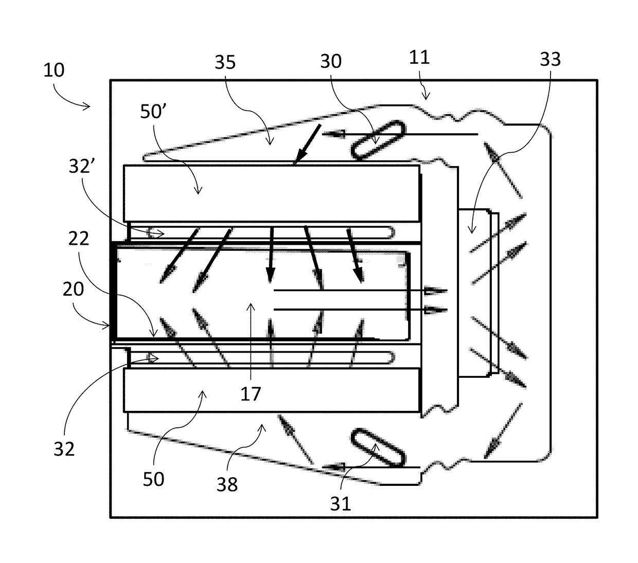
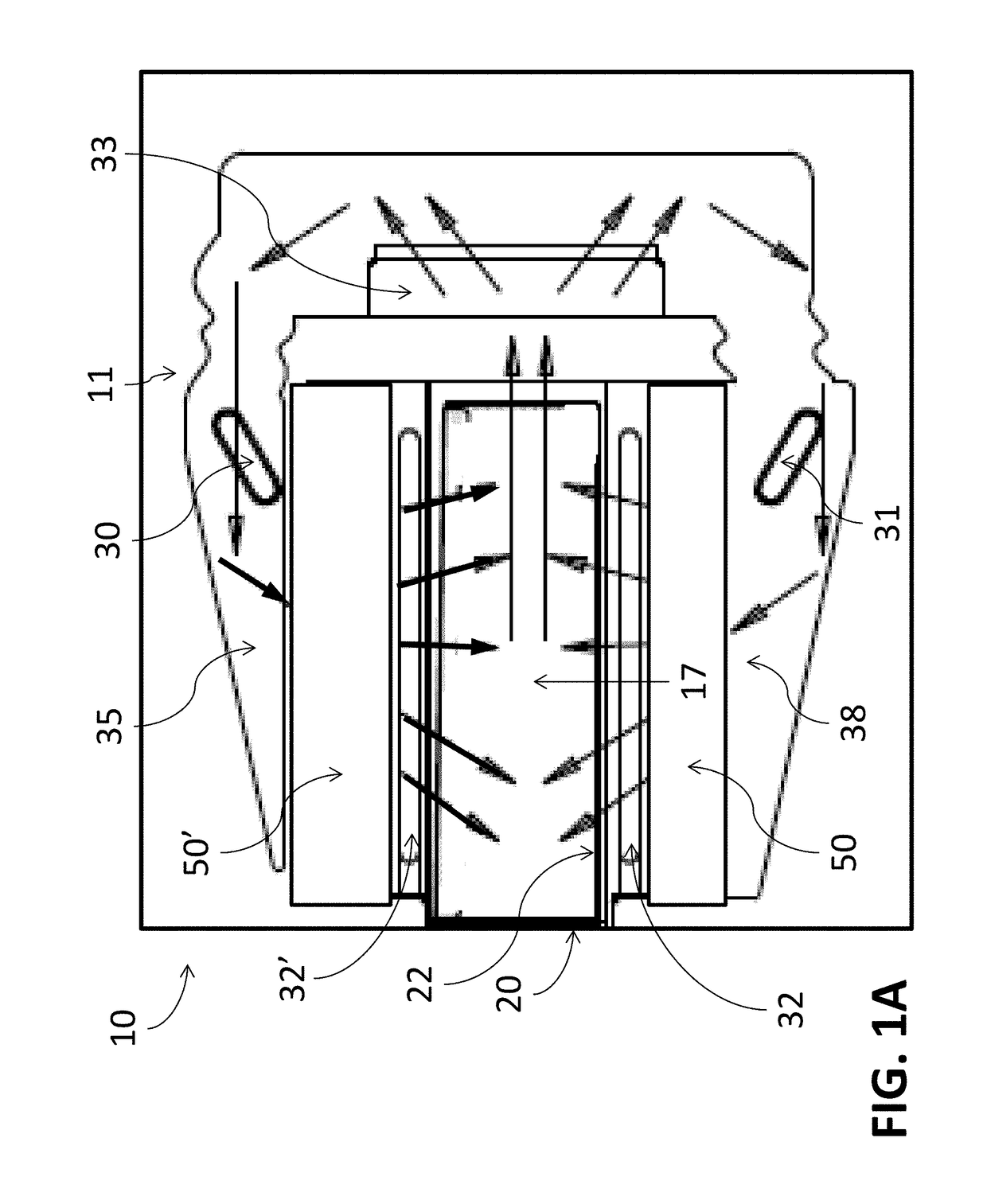
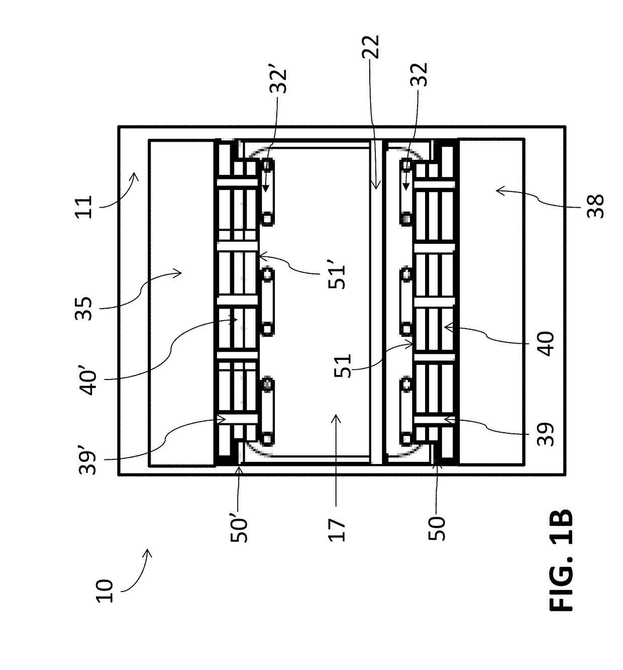
[0063]Referring now to the drawings and in particular to FIGS. 1A and 1B, there are depicted respectively side and front cross-sectional views of an oven, in accordance with an exemplary embodiment of the present invention. As shown, an oven 10 includes a housing 11, a cavity 17 located within the housing, and an oven door 20 for covering an opening to the cavity, through which a food item may be loaded on a food loading section 22 in the cavity for cooking.

[0064]The oven 10 includes a heating and airflow system to supply heat to cavity 17 for heating up any food items that have been placed within the cavity 17. The heating and airflow system may include a top air heating element 30 for heating air in a top air plenum 35, and / or a bottom air heating element 31 for heating air in a bottom air plenum 38. The heating system may also include a top infrared (IR) heating element 32′ located below the top air plenum 35, and / or a bottom IR heating element 32 located above the bottom air ple...


PUM


Abstract

An oven comprising a housing, a cook cavity located within the housing, wherein the housing includes an opening to the cook cavity and the cook cavity is configured to receive a food item through the opening, an oven door for covering the opening, a heating element configured to heat an air within the cook cavity, an active vent interconnecting the cook cavity and an outside of the housing, and a controller operatively coupled to the active vent and the heating element is disclosed. The controller is configured to perform the steps of (a) turning on the heating element to initiate a cooking cycle, (b) keeping the active vent closed during an initial stage of the cooking cycle, (c) after the initial stage of the cooking cycle, opening the active vent, and (d) keeping the active vent open during at least a portion of a remainder of the cooking cycle.

Description

CROSS REFERENCE TO RELATED APPLICATION[0001]This application is a continuation-in-part of U.S. application Ser. No. 14 / 704,732, filed on May 5, 2015, the entire content of which is incorporated herein by reference.FIELD OF INVENTION[0002]The present invention relates to cooking ovens in general, and in particular to a cooking oven based on a combination of rapidly moving heated air and infrared heating element and also to a cooking oven having an active vent.BACKGROUND OF THE INVENTION[0003]Hot air convective cooking is achieved by directing rapidly moving heated air at the food. Hot air heated in an air plenum is introduced into the oven cavity via air channels interconnecting the air plenum and the oven cavity. In general, optimal cooking air temperatures are in the 450° F.-500° F. range for non-bakery items, and in the 375° F. range for bakery items.[0004]Infrared (“IR”) heating is another well-known cooking method, whereby electromagnetic waves emitted by a heat source (typicall...

Claims


Application Information

Patent Timeline
Patent Type & Authority Applications(United States)
IPC IPC(8): F24C7/08A21B1/24A21B1/26F24C15/32
CPCF24C7/085A21B1/245A21B1/26F24C15/325A21B1/22A21B2/00F24C7/046F24C7/087G06Q10/087G01C21/343
Inventor MCKEE, PHILIP R.JOHNSON, ALEX WAYNE
Owner OVENTION
Learn More