Image processing apparatus, image processing method, and non-transitory computer-readable storage medium

Active Publication Date: 2018-05-24
CANON KK
View PDF5 Cites 7 Cited by
  • Summary
  • Abstract
  • Description
  • Claims
  • Application Information

AI Technical Summary

Benefits of technology

[0013]The present invention has been made in consideration of the above proble

Problems solved by technology

Since, however, it is difficult to calculate a motion vector of one pixel, for example, it is assumed that the adjacent pixels of a pixel of interest have the same motion, and a patch having the pixel of interest at the center is set to calculate a motion vector based on the average space-time luminance change of the pixels in the patch.
The template matching and gradient method have a problem that it is impossible to detect a large motion or the detection accuracy is low.
Even if the correspondence obtained at a given resolution is erroneous, this modification processing modifies the data at the resolution, and the erroneous correspondence is difficult to be propagated to processing of a next high-resolution image.
Then, if the processing result of the reduced image is processed as an input at a level at which the resolution is higher, the erroneous motions are unwantedly propagated to the next level.
As a result, in the final optical flow as the processing result of the equal-magnification image, the correctness of the optical flow of the boundary of the moving object becomes low in some cases.
Note that Japanese Patent Laid-Open No. 2001-148012 describes “if evaluation of reliability and m

Method used


Image

  • Image processing apparatus, image processing method, and non-transitory computer-readable storage medium
  • Image processing apparatus, image processing method, and non-transitory computer-readable storage medium
  • Image processing apparatus, image processing method, and non-transitory computer-readable storage medium

Examples


first embodiment

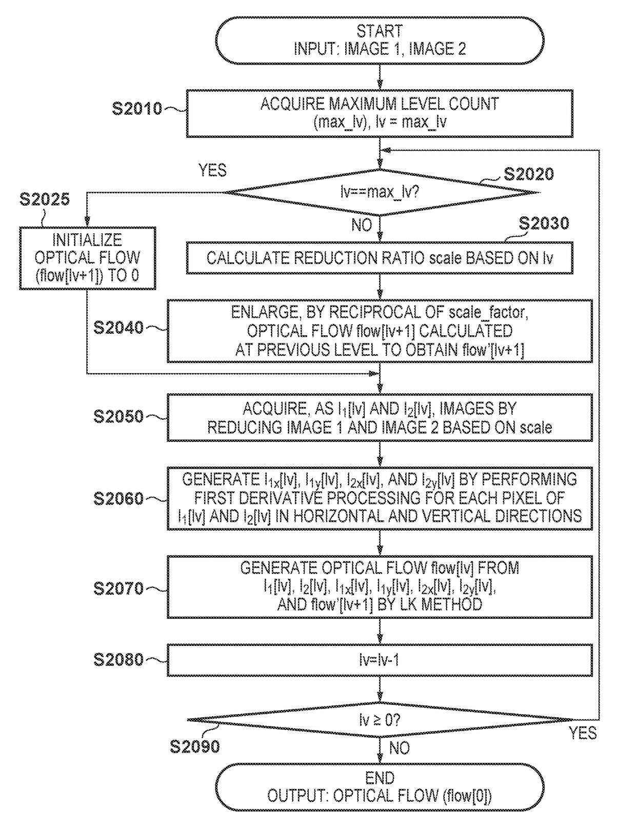
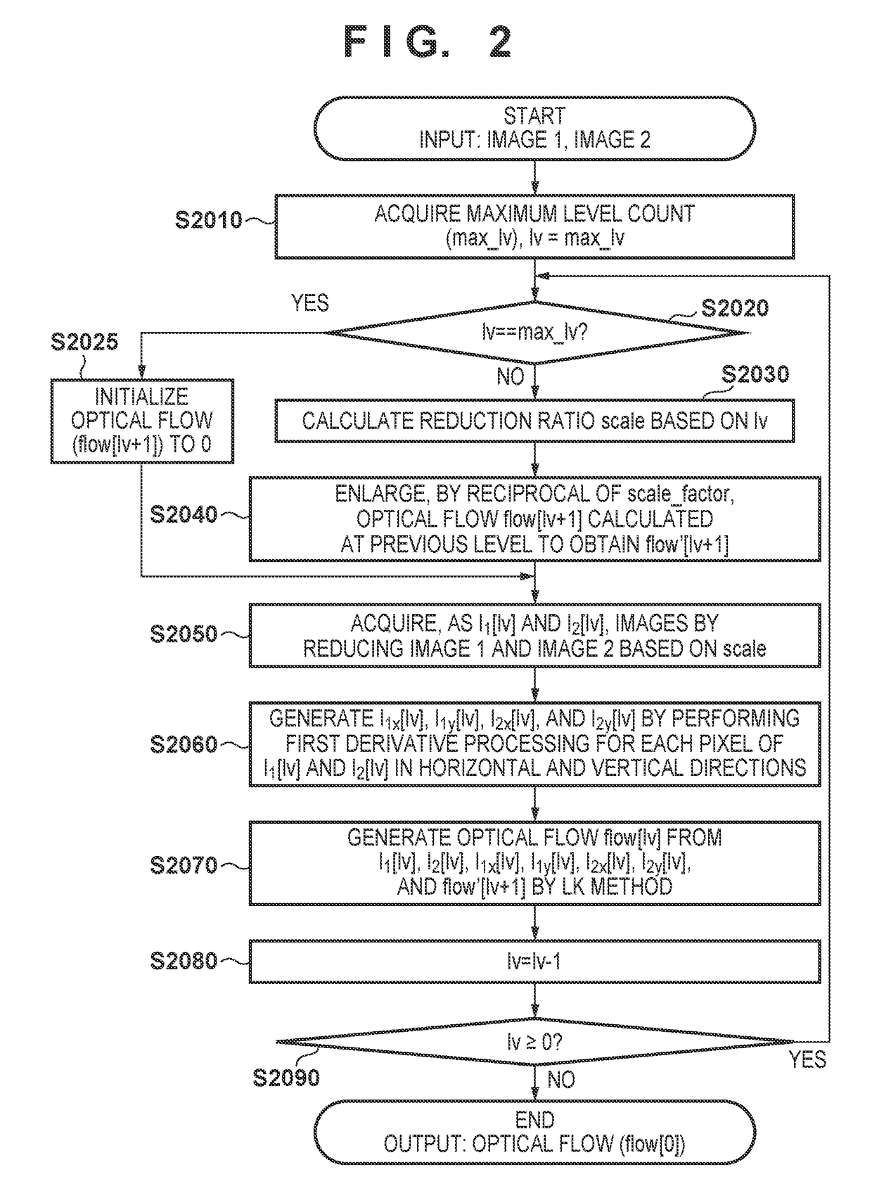
[0042]In this embodiment, an example of an image processing apparatus having the following arrangement will be described. This image processing apparatus acquires, as the first acquisition image, each of the first image and a plurality of reduced images obtained by reducing the first image in ascending order of image size. The image processing apparatus acquires, as the second acquisition image, each of the second image and a plurality of reduced images obtained by reducing the second image in ascending order of image size. The image processing apparatus generates a converted optical flow by converting, in accordance with the size of the currently acquired second acquisition image, an optical flow generated for the previously acquired second acquisition image. The image processing apparatus specifies, among motion vectors corresponding to a plurality of positions with reference to a coordinate position of interest in the converted optical flow, one or more motion vectors in ascendin...

first modification

[0083]In the first embodiment, the pixel positions dealt by the function given by equation (12) are limited to integers to reduce the interpolation calculation amount. However, if it is unnecessary to reduce the calculation amount, the pixel positions having real numbers may be processed intact, and the SAD may be calculated using interpolated pixel values. In the first embodiment, to extract corresponding points having higher likelihood of correspondence, the SAD is obtained as a difference. However, the present invention is not limited to the SAD, and an SSD (Sum of Squared Difference) or a weighted SAD or SSD may be used. Furthermore, the feature amount of a pixel such as a SIFT feature amount is represented by a multidimensional vector, and its norm may be used as an index. In this case as well, as the norm is smaller, the likelihood of correspondence is higher.

second modification

[0084]In the first embodiment, a motion vector corresponding to the smallest one of the 13 SADs is used to determine flow″[lv+1](C). However, the average of the motion vectors corresponding to the smallest and second smallest ones of the 13 SADs may be used as flow″[lv+1](C). In this case, flow″[lv+1](C) can be obtained by equations (17) to (19).

j0=argmin0i(sad(I1[lv],C,I2[lv],C+round(flow′[lv+1](C+Yi))))(17)j1=argmin1i(sad(I1[lv],C,I2[lv],C+round(flow′[lv+1](C+Yi))))(18)flow″[lv+1](C)=(flow′[lv+1](C+Yj0)+flow′[lv+1](C+Yj1)) / 2(19)

[0085]Note that the average of the motion vectors corresponding to the SADs from the smallest SAD to the pth (p is an integer of 3 (inclusive) to 13 (exclusive)) SAD among the 13 SADs may be used as flow″[lv+1](C).


PUM


Abstract

One or more motion vectors is specified in ascending order of a difference between a pixel value at a position C in I1 [lv] and a pixel value at a position separated, in accordance with a corresponding motion vector, from the position C in I2 [lv] among motion vectors at a plurality of positions with reference to the position C in flow′ [lv+1]. A flow [lv] is generated using flow″[lv+1] including, as an element at the position C, one motion vector based on the one or more motion vectors, I1 [lv], and I2 [lv].

Description

BACKGROUND OF THE INVENTIONField of the Invention[0001]The present invention relates to a technique for obtaining an optical flow between images.Description of the Related Art[0002]In recent years, a technique of associating pixels between two images is becoming increasingly important. The correspondence indicates the relationship between a pixel of a reference image and a pixel of a test image, which is considered to be identical to the pixel of the reference image, and can be expressed by the coordinates of two points. If stereo images are input, the depth position of a pixel can be calculated based on the positional relationship between the two points, and is applicable to three-dimensional image processing. If successively sensed images (a moving image) are input and the correspondence between the images is expressed by relative coordinates, the correspondence serves as a motion vector. The use of an optical flow as a set of motion vectors enables analysis of a moving object, no...

Claims


Application Information

Patent Timeline
IPC IPC(8): G06T7/285G06T7/13G06T3/40
CPCG06T7/285G06T7/13G06T3/40G06T2207/10016G06T7/246G06T7/269
Inventor KOBAYASHI, MASAAKINISHIYAMA, TOMOHIRO
Owner CANON KK
Why Eureka
Try Eureka