Floating structure and method of intalling same

Active Publication Date: 2018-05-31
ESTEYCO ENERGIA +1
View PDF31 Cites 10 Cited by
  • Summary
  • Abstract
  • Description
  • Claims
  • Application Information

AI Technical Summary

Benefits of technology

The present invention provides a floating construction for offshore use that is stable, safe, and economical. It consists of at least three taut retaining cables that are attached to a flotation base and to downward impelling means. The retaining cables provide a downward force to the flotation base, increasing its stability. This invention is advantageous for deep water depths and is efficient, safely, and economical for installation and maintenance. It is also suitable for use as a substructure for wind turbines. Additionally, it can be easily repowered.

Problems solved by technology

This power escalation and the particularly demanding marine conditions in turn imply a considerable increase in the demands on the substructure that must support the turbines, which requires developing novel concepts for said substructure with increased capacity, optimum strength and a competitive cost, particularly if the substructure will be used in locations with great depth, which may be advisable in some circumstances.
Among the main drawbacks and limitations of known floating solutions are the following:The installation of substructures implies high costs related to the scarce and costly marine means for transportation, handling and lifting of the foundation, shaft and turbine elements.Steel has a limited duration in the marine medium due to the aggressive conditions of humidity and salinity, particularly in tidal movement areas.
Consequently, maintenance requirements are high and costly.
Together with the high sensitivity of metal structures to fatigue loads, this means that the useful lifetime of the metal components of the substructure is limited.Steel substructures are highly sensitive to collisions from ships, icebergs and drifting objects in general.There are uncertainties resulting from the variability in the cost of steel, considerably greater than that for concrete.Certain existing solutions present a limited stiffness for the substructure shaft, which limits the capacity for greater heights of the substructure and size of the turbines, particularly with foundation solutions with a limited stiffness, with is the most common situation in off-shore installations.Great dependency on specific marine means for lifting and transportation, which are in limited supply.
With a proper design, fatigue sensitivity is also very low.

Method used


Image

  • Floating structure and method of intalling same
  • Floating structure and method of intalling same
  • Floating structure and method of intalling same

Examples


Embodiment Construction

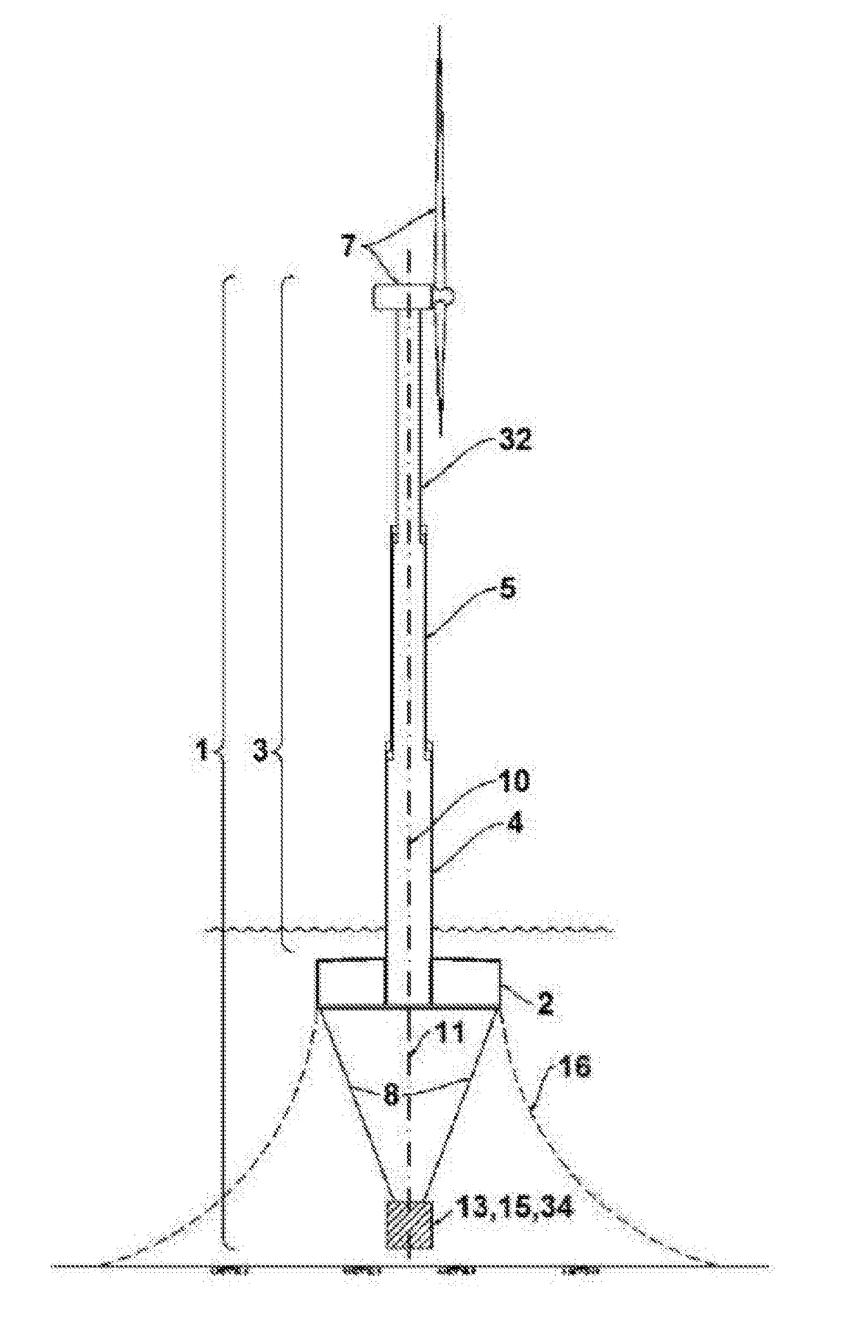
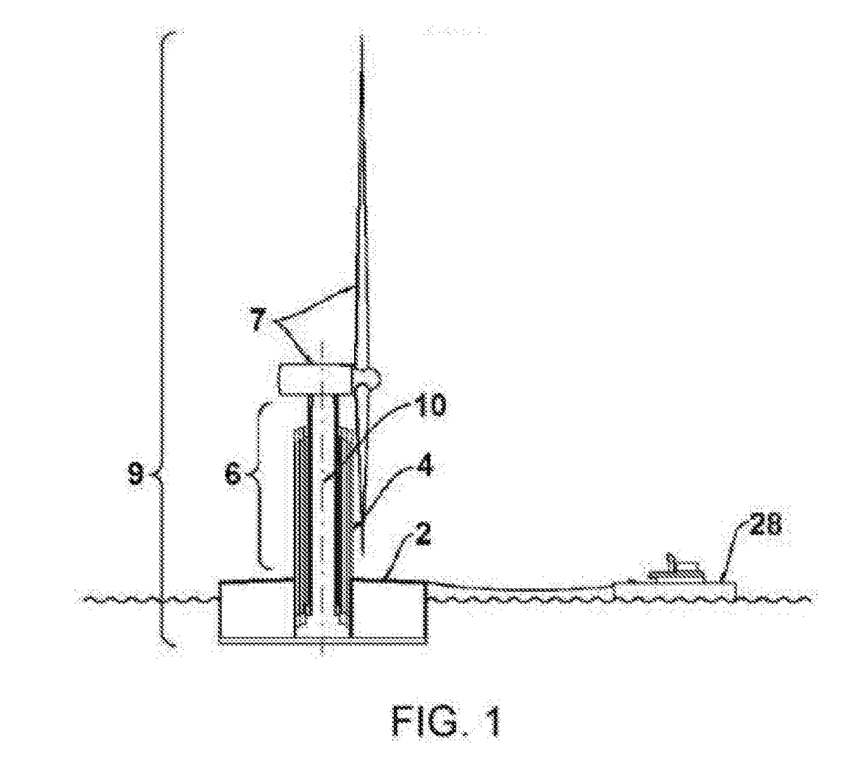
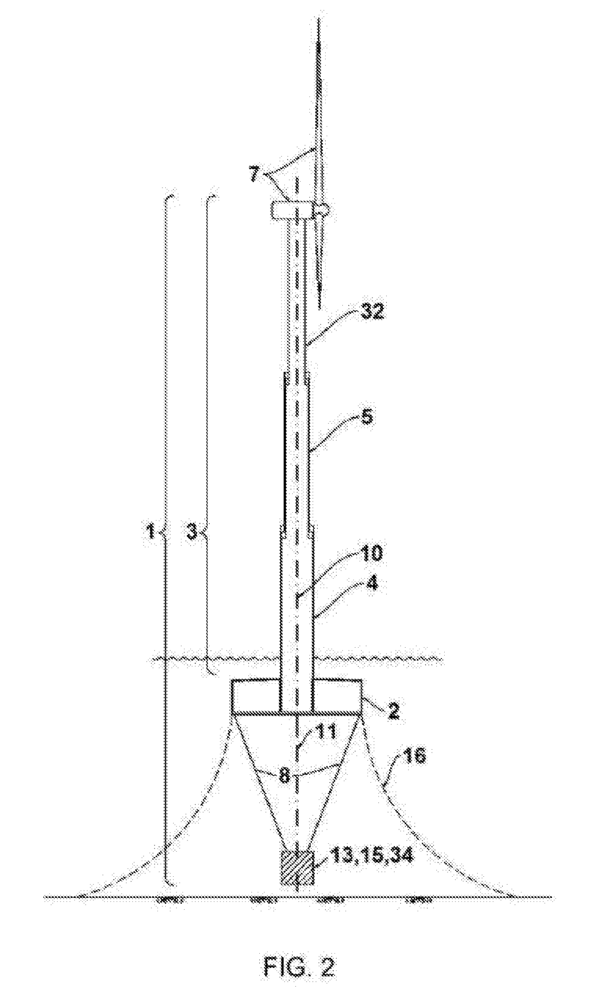
[0116]With reference to the accompanying figures, all of which show a floating construction which, in installed condition, according to the present invention, comprises: a floating base 2, which includes at least one body comprising at least a cavity 25, the maximum horizontal dimension of which is greater than its maximum vertical dimension; a building supported by said flotation base 2; downward impelling means; and at least three retaining cables 8 the corresponding upper ends of which are joined to said flotation base 2 and the corresponding lower ends of which are joined to said downward impelling means. In addition, in all figures except 8 and 11 the building that forms part of the floating construction comprises a telescopic shaft 3 where the wind turbine means 7 shown are an accessory that is optional and / or interchangeable with other accessories, depending on the use of the floating construction, illustrated only by way of example to describe the embodiments of the inventio...


PUM


Abstract

Floating construction comprising: a flotation base, comprising at least one essentially hollow body selectively fillable with ballast, where the maximum horizontal dimension of the flotation base is greater than the maximum vertical dimension of the floating base; a building supported by said flotation base preferably comprising a telescopic tower; downward impelling means; and at least three retaining cables the corresponding upper ends of which are attached to said flotation base, preferably in peripheral positions of the flotation base, and the corresponding lower ends of which are attached to said downward impelling means, such that said retaining cables are taut and apply a downward force on said flotation base that increases the stability thereof. And the installation method for this floating construction.

Description

CROSS REFERENCE TO RELATED APPLICATIONS[0001]This is a U.S. national phase of International Patent Application No. PCT / ES2015 / 070412, filed on May 27, 2015. Priority under 35 U.S.C. § 119(a) and 35 U.S.C. § 365(b) is claimed from Spanish Patent Application No. P201430794, filed on May 27, 2014.FIELD OF THE INVENTION[0002]The present invention relates to a floating construction intended to be installed accordingly in a location on a body of water, a lake or the like, and a method for installing the same.[0003]The construction of the present invention can be a floating substructure for a wind turbine, made in part from concrete, which in an installed condition comprises either a semi-emerged shaft and a submerged flotation base, or an emerged shaft and a semi-submerged flotation base. In this context the term “substructure” refers to the part of a wind tower intended to support thereon the generation means of the wind tower, therefore including the tower itself or shaft.[0004]For the ...

Claims


Application Information

Patent Timeline
IPC IPC(8): B63B35/44F03D13/25B63B21/20B63B17/00B63B21/50
CPCB63B35/44F03D13/25B63B21/20B63B17/00B63B2207/02E02D5/22E02B9/08B63B2035/446B63B21/50Y02B10/30F05B2240/9151F05B2240/93F03D13/10B63B21/502B63B2035/442F03D13/40Y02E10/30Y02E10/727Y02E10/72F03D80/00B63B2209/20Y02E10/728B63B21/26
Inventor FERNANDEZ GOMEZ, MIGUEL ANGELGARCIA CONDE, JOSE SERNA
Owner ESTEYCO ENERGIA
Why Eureka
Try Eureka